Hello all,
I have a lehmann Audio Black Cube SE II that had a blown channel.
Got the replacement opamp THAT 1510. When I went to replace it there was a resistor across pins 1&8 only on one channel.
This is supposed to set the gain, but wouldn't there be one on both channels?
BTW it sounds balanced
thanks
mdr
I have a lehmann Audio Black Cube SE II that had a blown channel.
Got the replacement opamp THAT 1510. When I went to replace it there was a resistor across pins 1&8 only on one channel.
This is supposed to set the gain, but wouldn't there be one on both channels?
BTW it sounds balanced
thanks
mdr
there was a resistor across pins 1&8 only on one channel.
Are you sure? The two channels seem to be laid out the same.
Is a resistor is missing in one of the footprint positions?
http://www.audiocostruzioni.com/r_s/giradischi/lehmann-audio-black-cube-se-II/dett 2.jpg
Definitely, the resistor was soldered to the backside of the pcb ( bottom)
If one resistor is really missing, you should install one that matches the other channel.
Is there any sign that one was soldered in place and removed, or are the pads solder free?
If one was never installed, you should tell Lehmann about this, they'll appreciate it.
Last edited:
Hi,
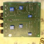
a resistor on the bottom is certainly a modification not present in the original.
The fixed MM-gain resistor between pins 1 and 8 of the THAT chip is a 220R 1% metal film.
A second resistor of 22R can be switched via Dip-switch pos1 of SW101/201 for the higher MC-gain.
The only off-the-shelf modificatioon on the PCB bottom side are the two soldered wire bridges that put the input stage into unbalanced mode.
jauu
Calvin
Attachments
Thanks for all the replies.
Upon further investigation the power supply isn't balanced. one side outputs 15v the other side 15.4. the higher side is where the resistor is attached to the back of the PCB.
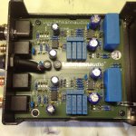
Attached is the closeup of the adjusting resistors for the power supply.
one side is 120 and 1.3k the other is 240 and 2.7k. this doesn't make much sense.

Here is the top of the Cube , all resistors match side to side

Upon further investigation the power supply isn't balanced. one side outputs 15v the other side 15.4. the higher side is where the resistor is attached to the back of the PCB.
Attached is the closeup of the adjusting resistors for the power supply.
one side is 120 and 1.3k the other is 240 and 2.7k. this doesn't make much sense.
Here is the top of the Cube , all resistors match side to side
Last edited:

Hi,
iIrc the datasheet of the LM317/337 regs shows feedback resistor values around 240R-270R and around 2k5-3k3 for the upper feedback resistors.
The set of 120R/1k3 results in similar output voltage, but represents probabely not the original values.
The soldering of the modded gain resistor looks very non-professional ... heck even the casings of both(!) nearby Dip switches are molten.
jauu
Calvin
Hi,
The soldering of the modded gain resistor looks very non-professional ... heck even the casings of both(!) nearby Dip switches are molten.
jauu
Calvin
ooops, my bad soldering angle on resistor and dip switches 😱
But the resistor didn't look that much better before I replaced the opamp.
Any idea on why the values are so far off? Other than a mistake?
do you think they tried to compensate for the added voltage with the extra resistor on the back?
I'll order a few resistors that should conform better too the data sheet.
Or should I get a multi turn pot, and dial it in?
thanks
mdr
Last edited:
Hi,
I don't know why the second set of resistors is lower in value .... maybe those resistors had been flying around. 😉
For that added bottom side resistor .... it looks as if the colour code would read brown-white-black-red-violet, hence 19k 0.1%.
Paralleled with the original 220R the difference in gain is probabely only measurable but sonically irrelevant.
Still though I'd rather change back to the original state.
jauu
Calvin
Calvin,
Thanks so much for your help.
here is a larger image of the resistor in question

So I'm going to find another set of resistors to match both half of the power supply. Then remove the resistor on the back of the phono board.
Sound about right?
On to another topic. Would there be anything to be gained by changing out the caps for more exotic versions?
thanks again
mdr
Thanks so much for your help.
here is a larger image of the resistor in question
So I'm going to find another set of resistors to match both half of the power supply. Then remove the resistor on the back of the phono board.
Sound about right?
On to another topic. Would there be anything to be gained by changing out the caps for more exotic versions?
thanks again
mdr
Hi,
now this looks tather like orange-white-black-brown-brown, which would be a 3k9 1% resistor.
Paralleled with 220R the reduction from 220R would even be less than with 1k9, app -5%.
This is hardly audible at all.
It's not obvious to me why this mod had been done ..... maybe the pickup used showed a inter-channel sensitivity imbalance that was corrected for by this gain modification.
The Lehmann itself certainly shows suffificiently precise matched channel gains.
jauu
Calvin
Well I fixed the power supply with a pair of trimpots to get 15v exactly. Then I removed the patch resistor from the back of the cube. Everything is working fine. thanks for the help!
Now the question is whether or not to replace the gain resistors. so I can match my dac.
Now the question is whether or not to replace the gain resistors. so I can match my dac.
Hi,
The Q of changing gain is easy ... and then it isn´t 😉
First You needed to know the level difference between DAC output level and Phono output level.
Is it really annoying -or such a big difference- to ´equalize´ the volume levels with the preamps volume pot?
If so, the Lehmann´s gain can be set at two points ...
first, between MM and MC by switching between +33.3dB (MM, 220R) and +53.2dB (MC, 22R) ...
second, between +22.5dB and +32.1dB in the second gain stage (OPA134, SW102/202 No.1, marked ´+10dB´).
Have You already tried to +10dB?
If not, the prime way to change overall gain would be to increase the gain of the first stage, the THAT1510.
The gain-formula of that chip reads Av=1+10k/Rg and Av[dB]=20x log(Av)
22R (R108/208) and 220R (R197/207) will give the above stated figures.
The ~+53dB are already close to a sensitive limit of the THAT.
The upper gain limit of 1.000 (+60dB) cited in the Datasheet should not be exceeded by much, as bandwidth limit and noise may become issues.
Hence a gain increase of 2x (+6dB) can be accepted and achieved with a paralleled 220R and/or 22R ... or by replacing the original 220R/22R with 100R/10R.
Since the second gain stage is linear it´d be possible to increase the gain beyond +32dB, but I wouldn´t recommend that, as +32dB is already quite alot for a simple OPamp gain stage.
But paralleling the 100R resistors (R114/214) with a second 100R or replacing by 51R or 47R raises the gain by ~6dB to +36dB to +37dB will do that job if wished for. 😉
jauu
Calvin
- Status
- Not open for further replies.
- Home
- Source & Line
- Analogue Source
- Lehmann Audio Black Cube SE II question