Years ago (1987 December) a magazine called Modern Electronics had an article called "A $149 Digital Stereo Amplifier" by C. Barry Ward.
Besides the magical "digital" word in the title, the article was a howto with schematics, board layout and instructions on building a Class D amplifier. Since Modern Electronics appears to be long out of print and I can find no information on the author of the article, I was wondering on the legalities of posting diagrams or any part of the article.
A lot of the information I've read in this forum has cleared up some of the design tactics of the circuit and I'm wondering how the amp would be assessed by todays Class D afficionados.
But of course I wouldn't want to post any of the article in question if there were legal restrictions of any form.
Anybody know or care to comment?😕
It depends on who owns the copyright these days. If anyone. And determining that could be difficult.
To be safe, you could probably post just the schematic portion; since you're interested in discussing it and are not posting substatial portions of the article, it most likely falls under the Fair Use doctrine.
usual disclaimer: I am not a lawyer and this should not be construed as giving legal advice.
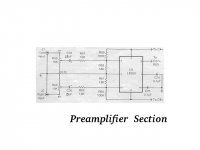
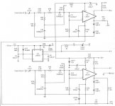
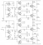
Well here are the schematics, they consist of the preamp section, the pwm section and the driver/power stage.
Any comments on this design. Consider it was 1987 and the MOSFETs used though not great by today´s standards, they were quite good.
I only briefly had mine working on the test bench back at college, before I blew something up. I played around with a fews mods but never got the time to finish before more important things (assignments and tests) got in the way.
Attachments
Seems like the second and third stage jpgs are too big. Bear with me and I´ll rescan and reduce the pages.
Hi,
Thanks for deciding to post that after all.
Seems to me it's what you might consider to be the classical text book class d because it's so very basic.
Neat way to see the full bridge done, but far from optimal. I think it's great from a small DIY sub amp learning experience perspective. This is not a good example of the open loop concept.
Regards,
Chris
Chris,
How would you improve the design?
Would it be easy to close the loop and/or perhaps filter better at the output? I, too considered this as a possible sub amp, but I gave up on it long ago. What I found interesting is that the author of the article used some of the same descriptions we have all heard regarding the Sonic Impact and other of the D and T-amps; "no audible background noise", "transparent", "superb transients", and "exceptional sound depth". And this was the amp as configured in the article, full range and untweaked.
I have considered rebuilding the board and tweaking but really don't know where to start. I've been out of this a rather long time.
One of the questions I have is how the self oscillating frequency can be determined. The author claimed 250kHz and I measured about 180kHz and couldn't determine the reason for the discrepancy.
Slowly getting back into this ...
pepolman said:Chris,
How would you improve the design?
Would it be easy to close the loop and/or perhaps filter better at the output? I, too considered this as a possible sub amp, but I gave up on it long ago. What I found interesting is that the author of the article used some of the same descriptions we have all heard regarding the Sonic Impact and other of the D and T-amps; "no audible background noise", "transparent", "superb transients", and "exceptional sound depth". And this was the amp as configured in the article, full range and untweaked.
I have considered rebuilding the board and tweaking but really don't know where to start. I've been out of this a rather long time.
One of the questions I have is how the self oscillating frequency can be determined. The author claimed 250kHz and I measured about 180kHz and couldn't determine the reason for the discrepancy.
Slowly getting back into this ...
Honestly, I really wouldn't.
I think the 555 is just being used as a mute switch, so from what I see it's not seetting frequency.
I dont' know exactly whatl E11 and E12 are for, perhaps mixing an external clock.
Otherwise I'd imagine the frequency would be dertermined by the mess of RC networks at the input to the comparators.
I don't like the amount of transistors in this circuit I think it's very excessive for the job they're doing, and in this particular case I dont' even see them making full use of the chosen comparators either, so I'd work on it by simplyfing everything from the modulator, rather going with a more basic hysteretic converter which would make it easier to close the loop.
I think circuit would be brutal for timing errors, and there isn't even hysteresis used to to ensure a nice clean switch on the comparator.
I also prefer an all N channel output stage, with at least an LC filter.
In short there's nothing I wouldn't change on this.
If you want to try and build yourself a homebrew discrete class d amp I can point you to a more worthy one to put your efforts towards, or just search around the forums for projects others have done, see which you like best.
It's actually hard to miss getting those characteristics you mentioned with even the worst possibly crackling class D it's just the nature of the beast, although I think the author might have been exagerating just a little bit with this particular circuit.
- Status
- Not open for further replies.
- Home
- Amplifiers
- Class D
- legalities of posting schematics from a defunct magazine