Well, you have the amp biased for AB operation even though it's single ended. Are you using some OPT's that you feel are too small to handle more than 32mA?
I have it slightly under biased so it doesn't run too hot since the amp is being used a lot. Tubes last longer and PT doesn't get hot. I made it to be reliable rather than getting the max power out of it. Maybe another reason it survived no load.
I think that is merely a philosophical issue. What makes a pentode a pentode? Every grid can be used as a signal input, and one of the qualities of a pentode is that there's not one grid to drive but two (and sometimes even three). The fact that the most basic pentode circuit (and the one for which characteristics are given in the datasheet) uses a fixed DC voltage on G2 doesn't rule out other ways to use the tube for being somehow a "less pure" pentode.
Perhaps semantics here or such. I agree with you, but was trying to talk about classic pentode operation, i.e. constant voltage between cathode and screen so as to 'give' to the anode a kind of constant current source - the way pentodes were employed originally. It obviously works with screen bypassed to earth even with NFB to cathode or the designs would not exist.
Impression is created that grounding the screen bypass cap was more habit than 'innovation'. (It also occurred in several other power amplifiers viz. some of the later Leaks and such). If it was purposely done one would axpect some kind of claim as to why and explanation of the operation (i.e. with a signal source in the screen in the equivalent diagram) or at least with claim to improved souind. Thusfar I could not find any explanation as to why one would deliberately bypass a screen to earth in the presence of NFB (to the cathode).
But going OT, back to topic.
Multicaps had common negative lead on their body, and a chassis routinely was used as a common wire, that's why screen grids were bypassed to ground. Just "good enough for given price".
Well I'll be ....
Never considered that, not having had to do with such an amplifier on my bench. But that would certainly explain the occasionally rediculously high values for such caps. They were all electrolytics - might very well have been part of a multicap!
Never too old to learn - me, that is. Thanks, A! 😀
(I always thought that having a 4µF or similar cap decoupling several 100K was curious, setting the -3dB frequency in the 0,2 - 0,4 Hz regions; usually such caps fell into the 0,1 - 0,5µF region.)
??? I am not in this thread.....
But you have a beard on your avatar! 😀
Johan., what is signal 'bottowing'?
AAARGH!!!

Missed that one -
But I have this problem with my PC; it persists in turning letters upside down (one phase inverter too many somewhere ....)
Johan,
My Mac computers have good keyboards (no "phase inverters" inside)
But the problem is that if I type a word that it does not know, it automatically replaces it with the closest word it knows how to spell. @#$%^&*
My Mac computers have good keyboards (no "phase inverters" inside)
But the problem is that if I type a word that it does not know, it automatically replaces it with the closest word it knows how to spell. @#$%^&*
One more "try":
The unloaded secondary of a ParaFeed Amplifier.
The answer that was given earlier in this thread about power up and power down
causing the low frequency voltage change to resonate the circuit was correct.
A Hot-Start might do the same.
Another potential problem (pun intended) is shown in the attached schematic.
The 10 uF and hi-Q 200H primary will multiply the triode output voltage.
The tube, 10uF, or 200H OPT might arc over.
Attachments
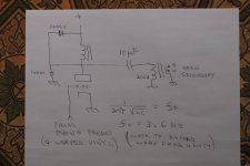
Nothing will arc over on such a resonant frequency. Be realistic. If it clips, it clips on 42 Hz and above. On 3.6 Hz the core will saturate on 1/10 Th of a max voltage for 42 Hz output.
Aahhh, some fresh practical thinking. Good one, Wavebourn. Didn't think of that!
Just a maths and physics versus rules of dumbs! 😎
Read and article about Bruno:
https://www.soundandvision.com/content/bruno-putzeys-head-class-d
Also, we discussed here recently his article about feedbacks and stability. Great approach, to apply knowledge to design instead of following beliefs & fashions! ;-)
Last edited:
Great approach, to apply knowledge to design instead of following beliefs & fashions! ;-)
I couldn't resist. Another sound basic principle, so often neglected because the right way is laden with 'boring mathematical gymnastics'.
[Wavebourn getting better all the time - posted several valuable basics in this thread ... 😀 😀 😀 ]
[Wavebourn getting better all the time - posted several valuable basics in this thread ... 😀 😀 😀 ]
"When I was a teenager my parents were so dumb and boring, now they grew up so smart and funny!" 😀😀😀
Wavebourn was right.
He got me thinking about the series resonant circuits I posted in this thread.
The OPT should be OK, even if the Parafeed amp was unloaded.
Even if the OPT did not saturate at low frequencies, the impedance at series resonance would approach the DCR of the OPT (a very low impedance).
Pentodes, and even Triodes would not drive very much voltage into such a low impedance, so even with the voltage multiplication due to Q, it would not likely stress the voltage capabilities of the series capacitor and OPT (Parts which had high enough voltage ratings to work properly when the output IS loaded).
Wavebourn was right.
Thank you. 🙂
Among other things I shared with Community Gyrator load of triodes and 4P1L tube. ;-)
- Status
- Not open for further replies.
- Home
- Amplifiers
- Tubes / Valves
- Left my amp on without speaker for hours