Not impossible, but very unlikely. However, due to the absence of a screen grid resistor, the screens are easy to blow. G1 stoppers are also not present, but the 6V6 and 6SN7 are not exactly high transconductance types, so he'll probably get away with that too. It prevents the introduction of extra poles, so it is good for overall loop stability.
My favorite quote from this article:
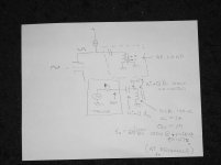
New Phase Splitter
New Phase Splitter
So true...the use of grid stoppers in feedback amplifiers is to be deplored unless they are absolutely necessary
I tend to think screen grid damage will happen before OT insulation breakdown.OPT insulation breakdown is the thing to look out for..
Sent from my phone. Please excuse any typpos.
I tend to think screen grid damage will happen before OT insulation breakdown.
Maybe in this simple amp, yes.
Insulation breakdown is instantaneous, screen meltdown takes time.
In an overdriven guitar amp that suddenly blows its speaker, an OPT can erupt in flames with the resulting B+ to ground (grounded OPT secondary) arc taking out the line fuse and killing power. The output tubes are often still good.
But I've build this amp and made sure I have headroom for errors.
But I was mainly asking what happens to output tubes running with no load (speaker). The dissipation must go somewhere but plates weren't glowing or anything.
Well, you have the amp biased for AB operation even though it's single ended. Are you using some OPT's that you feel are too small to handle more than 32mA? Those babies are dropping over 20v. You need to add some 5K screen resistors and get that voltage under the plate voltage.
I am in a difficult position here finding errors in replies and articles not directly related to the original topic. I hope 6V6dude will have some leniency!
My reference is mainly to the quoted article from Dr Bailey. I will briefly mention my difficulties, not going into such to respect the topic.
1. He mentions regarding a cathodyne phase splitter directly coupled to an input tube: '.... loads that drive the output stage is balanced but the output impedances are not'.
This is a common mistake eminating from a cursory look, where the cathode impedance appears lower that the anode output circuit. But the two impedances are equal, because the same cathode current flows in both circuits. Provided impedances at the driven load are equal, both signals and impedances are equal.
2. In the Radford phase splitter, the first stage does not operate in pure pentode way. Bypassing the screen grid to earth instead to the cathode puts a signal between it and the cathode, vaguely resembling UL operation. Pure pentode operation is only achieved with screen bypassed to cathode, irrespective of what goes on outside the pentode.
[The same compromise occurs to a significantly greater extent when global NFB for a complete amplifier, is applied to an input pentode's cathode, while the screen is bypassed to earth instead of to the relevant cathode. In this case a signal some x 10x the g1 input signal, appears in the equivalent circuit as a generator in the screen circuit. Analysis and practical measurements prove such a difference.]
3. I must disagree with the pronouncement that grid stoppers are bad. The reason is not mentioned that I can recall, but if Miller effect is again meant, with pentodes such an effect is minimal compared to other h.f. affecting elements. In fact, I use large G1 stoppers (10K) which does nothing mentionable to ordinary operation, but can noticably mellow effects of signal 'bottowing'.
I myself have often found the open loop b.w. of a tube amplifier go to -3dB well outside the audio range, and I never had much trouble in attaining stable GNFB up to gnfb firgures of 30 dB. Regarding the l.f. stability, I am currently building a very stable 100W amplifier (mentioned elsewhere on this forum) with all of 5 l.f. poles (including the OPT), with complete l.f. stability. (Admittedly two are step poles reverting back to 0° well outside the audio spectrim.) I do not maintain such is common practice, simply that if one follows the basics one can handle most instabilities.
Dr. Bailey and myself appear to have had different experiences regarding the design of tube amplifiers.
As said not to go further off-topic, but since the door was opened .....Thanks for allowing this, 6V6dude.
Last edited:
Johan, that's a good summary, anecdotally, the fact that the Bailey/Radford phase splitter never caught on also speaks volumes.
One more amp that you should not run without a load:
A Parafeed SE amp (with or without negative feedback).
If there is any signal at the input, and if it is at a frequency that matches the resonance of the Parafeed coupling cap and the Parafeed output transformer inductance, it will have a max current at resonance (and max voltage at the junction of the parafeed capacitor and the parafeed opt primary). If the component Qs are good, these voltages will exceed the plate voltage swing, by several times.
You may or may not hear the arcing.
One more amp that you should not run without a load:
A Parafeed SE amp (with or without negative feedback).
Easy to protect by damper diodes, like a PP amp.
Wavebourn,
Huh?
Damper diodes connected across the resonant point and ground?
(from the common point of the Parafeed series Cap and the OPT primary, to ground)?
Can you draw a schematic, and give some general values, please?
What kind of damper diodes?
Huh?
Damper diodes connected across the resonant point and ground?
(from the common point of the Parafeed series Cap and the OPT primary, to ground)?
Can you draw a schematic, and give some general values, please?
What kind of damper diodes?
I believe johan may have meant bottoming, not bottowing.
Or in other words, clipping.
Grid stoppers do change the effect of the signal going to the control grid if/when it goes positive versus the cathode. It reduces the grid current, and more importantly smooths the shape of the clip (less of the high frequency versus without grid stopper). No, I am not talking about the resistor/miller effect, rather the resistor/grid diode curve.
I use grid stoppers too.
I do not like to clip any amp, but if the gain is turned up to high for a portion of the music, it does not have as much cacophony during the clip.
Last edited:
Damper diodes connected across the resonant point and ground?
(from the common point of the Parafeed series Cap and the OPT primary, to ground)?
No. Before the coupling cap, to B+ and to ground. In PP amps I use damper diodes across both output tubes to ground. In parallel with GU-50 I use a pair of 1,000V dampers in series (800V B+)
Also, a little bit of extra compensation is needed for unconditional HF stability, actually. Sometimes a Zobel across output is good to add.
Screen grid protection is also very easy, using LEDs that flash on LDRs in input attenuators. Protected grids, and no clipping!
Speaking of grid stoppers, I use 4.7-15k after Concertina to output pentodes, and a cap to ground with zero grid stoppers in input pentodes.
All that problems are for people who copy examples from 1930'Th tube data books, instead of thinking.
thanks PRR....
i have seen the "tether diodes" in a guitar amp output circuit, composed of several diode strings of 1n4007's.....
i have seen the "tether diodes" in a guitar amp output circuit, composed of several diode strings of 1n4007's.....
An externally hosted image should be here but it was not working when we last tested it.
A 1000V snubber at the plate of a SE parafeed amp might not prevent over-voltage destruction when the output is unloaded, and there is signal present.
The attached schematic should explain that.
The attached schematic should explain that.
Attachments
Last edited:
The resonance should be well subsonic, so during normal use, there is no danger of overvoltage. I'd expect trouble when turning the amp on or off, because in the first case, the output tube is still cold while voltage comes up, and in the second case, voltage suddenly "plunges", and both events are dominantly subsonic. The coupling cap will likely go first. I think you raised an important, and often overlooked, point about parafeed here!
Stories about fire on amps comes from era, when concert amps were big pentode, huge things. Big anode voltages,full volume. Socket and transformer arcs.
Risk is small with "household" triodes.
Risk is small with "household" triodes.
A 1000V snubber at the plate of a SE parafeed amp might not prevent over-voltage destruction when the output is unloaded, and there is signal present.
The attached schematic should explain that.
Draw one diode from anode to B+, another one draw from anode to ground. And check again.
Johan Potgieter said in post 46:
1: That is indeed a mistake often made, and one that I didn't understand. Because I always thought that when a concertina splitter has the same (complex) impedance in the anode and cathode circuit (including the input impedance if the driven circuit), that their output voltages must be exactly opposite of each other, save for a slight imbalance caused by the tube's internal capacitances. The fact that so many people get this wrong (even respected names!) has made me doubt myself many times in the past...
jazbo8 said in post 47:
My reference is mainly to the quoted article from Dr Bailey. I will briefly mention my difficulties, not going into such to respect the topic.
1. He mentions regarding a cathodyne phase splitter directly coupled to an input tube: '.... loads that drive the output stage is balanced but the output impedances are not'.
This is a common mistake eminating from a cursory look, where the cathode impedance appears lower that the anode output circuit.
1: That is indeed a mistake often made, and one that I didn't understand. Because I always thought that when a concertina splitter has the same (complex) impedance in the anode and cathode circuit (including the input impedance if the driven circuit), that their output voltages must be exactly opposite of each other, save for a slight imbalance caused by the tube's internal capacitances. The fact that so many people get this wrong (even respected names!) has made me doubt myself many times in the past...
I think that is merely a philosophical issue. What makes a pentode a pentode? Every grid can be used as a signal input, and one of the qualities of a pentode is that there's not one grid to drive but two (and sometimes even three). The fact that the most basic pentode circuit (and the one for which characteristics are given in the datasheet) uses a fixed DC voltage on G2 doesn't rule out other ways to use the tube for being somehow a "less pure" pentode.2. In the Radford phase splitter, the first stage does not operate in pure pentode way.
That's indeed a bit too much black/white. Grid stoppers aren't bad, but many designers just throw them in without giving too much thought. Grid stoppers help prevent blocking/farting distortion, they prevent g1 overload and suppress spurious HF oscillation. So they have a right of existence. But they also introduce additional poles, which can badly influence GNFB loop stability in wide-bandwidth designs (not necessarily limited to audio power amps). So in case issues arise, grid stoppers can be removed with good effect, in places where the properties of the tubes and the circuit allow this.3. I must disagree with the pronouncement that grid stoppers are bad.
jazbo8 said in post 47:
There's a phletora of very good design ideas that somehow never caught on in audio. Most traditional designs are not outstanding, they are merely good enough. Many tube amps that are currently held in high regard have off-beat designs. Radford, McIntosh, Harman-Kardon and some more have produced collector's items by doing so. Reasons for staying "normal" include, but are not limited to cost cutting, time to market pressure, conservatism, lack of familiarity with alternative concepts, blah blah blah...the fact that the Bailey/Radford phase splitter never caught on also speaks volumes
Originally I've build it without NFB, sound was good but I wanted just touch tighter sound and to push the clipping at higher level bit further. This did the trick for me, not very noticeable but I can hear it. I don't like too much NFB, sound to transistorized to me.You might just as well go without GNFB altogether, it doesn't really influence anything at all here.
Is the voltage at the cathode of the 6V6 still around 21.5 V? If yes, go have a beer and forget about the whole thing.
BTW, is your volume pot really connected the way you drew it? That's not right.
And no I haven't checked the voltage. Sounds the same to me. I normally open it up and measure voltages when it starts sounding mushy and I need to change tubes. Probably will have to do that soon because I can hear little HF loss. But that also could be tubes in my 12AX7 preamp which runs all the time so I'll check them both.
The volume pot? Maybe it should be drawn backwards, it works as it should.
And thanks.
It's only a little thing, you can see here.
An externally hosted image should be here but it was not working when we last tested it.
Last edited:
- Status
- Not open for further replies.
- Home
- Amplifiers
- Tubes / Valves
- Left my amp on without speaker for hours