Hey,
Hoping someone can give me some help 🙂
I have an AKAI AM32 amplifier ( schematics link here : https://elektrotanya.com/akai_am-32.pdf/download.html , also attached ) and am having an issue with no output out of both the left side speakers. Also no output on the left side of the headphone jack. Have opened it up and given it a clean ( was very dusty ) and had a look at most solder joints which all seem to be in tact. The amplifier was left on for an extended period of time which may have contributed to the issue. I have checked the fuses and none were blown. Was working perfectly fine the day before and have been using regularly for the past year.
I have a voltage meter and a soldering kit. I have some previous experience with electronic but not a great deal with amplifiers.
Any help appreciated 🙂))
Thanks,
JB
Attachments
Hi JB,
Obviously, your first challenge is to do some fault isolation. The schematic you posted shows details on the right channel, but your problem is in left channel. I hope PCB silkscreen or other info makes it obvious how to navigate in the left channel. I'll reference parts in the right channel where Reference Designators are provided, but you'll have to find the corresponding parts in the bad channel.
"No output" could be due to a failure in the amplifier circuit or it might be a simpler inadvertent open connection in the signal path--- in either output or input. Perhaps the easiest initial test is to look at the output voltage at L101. It should be no more than a few mV. Large DC output indicates amp failure; but only a few mV would be at least encouraging. Does L101 voltage have continuity through the relay and onward toward speaker/headphones? Low DC output and intact output path would suggest an open at amp input.
Maybe this enough to at least get started.
Good luck!
Welcome to the forum!
I'd have a check of the speaker-protect relay (BSST mentioned), RL101. The unit is certainly old enough to have acquired some dust or oxidation on the contacts. Good that you mentioned the missing headphone line: Since the jack is just resistively attenuated main outputs, makes perfect sense.
Good luck
Cheers
Hey,Welcome to the forum!
I'd have a check of the speaker-protect relay (BSST mentioned), RL101. The unit is certainly old enough to have acquired some dust or oxidation on the contacts. Good that you mentioned the missing headphone line: Since the jack is just resistively attenuated main outputs, makes perfect sense.
Good luck
Cheers
Thanks for you replies ! 🙂
I am still a little lost and have quickly noticed that my seemingly lack of electronics knowledge is becoming much more evident. ._.
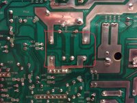
Just to confirm would this be the component sitting at RL101 ( https://www.benl.ebay.be/itm/2x-Omr...-24V-DC-Made-in-Japan-24VDC-NOS-/263588363215) it seems so. Ive attached a photo. On the top side of the PCB it is labeled with RL101 Are you able to help me through the diagnosis of the component, if i have the identified correct one ? Is it possible to diagnose with a voltage meter without desoldering the component?
Thanks for the help !
Hopefully I can save its life hehe
Attachments
Hey,Hi JB,
Obviously, your first challenge is to do some fault isolation. The schematic you posted shows details on the right channel, but your problem is in left channel. I hope PCB silkscreen or other info makes it obvious how to navigate in the left channel. I'll reference parts in the right channel where Reference Designators are provided, but you'll have to find the corresponding parts in the bad channel.
"No output" could be due to a failure in the amplifier circuit or it might be a simpler inadvertent open connection in the signal path--- in either output or input. Perhaps the easiest initial test is to look at the output voltage at L101. It should be no more than a few mV. Large DC output indicates amp failure; but only a few mV would be at least encouraging. Does L101 voltage have continuity through the relay and onward toward speaker/headphones? Low DC output and intact output path would suggest an open at amp input.
Maybe this enough to at least get started.
Good luck!
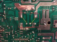
Thanks so much for your response. I believe I have identified the RL 101 component of the DC Relay. Attached is a photo of the region and the yellow lines are the pins i tested the voltage. The reading was around 65mV, does this indicate failure?
Apologies for the lack of knowledge but hopefully i can resurrect this amp 🙂
Thanks for the help
Attachments
Try to resolder the relay. The power soldering seem to have a breackage. Simply apply a small amount of tin with rosin (or flux) to recover soldering points. If the fault persists, try to short the relay contacts with a piece of wire. If its ok, then replace the entire relay or (it depends of your skills) may clean the relay removing the plastic cover and using sand paper of very very fine grane (800 or better). Clean with isoprophyl alcohol and let it dry. Thus re-place the relay in its place. I did such a task several time with industrial relays no longer available to replace.
I was suggesting you measure DC voltage from L101 to ground (eg. speaker ground binding post); this is essentially the amplifier output prior to the relay contacts and is a quick clue about health of the power amp. 65mV re ground is a bit higher than I would have expected, but not alarming. If your measurement was in fact Output to ground, you should observe the same 65mV on both sides of the relay output contacts and at the speaker binding post. (You should also find energizing voltage across the relay coil.). Osvaldo's advice is excellent if there's anything amiss re relay continuity.Hey,
Thanks so much for your response. I believe I have identified the RL 101 component of the DC Relay. Attached is a photo of the region and the yellow lines are the pins i tested the voltage. The reading was around 65mV, does this indicate failure?
Apologies for the lack of knowledge but hopefully i can resurrect this amp 🙂
Thanks for the help
This looks like the likely connections. If one channel is still working, there's no point in confirming energizing voltage on the relay coil -- the usual first check.
The traces to measure are across the contacts, one pair for each output. Anything over a couple/few millivolts with a speaker connected would be suspicious. You can measure on the AC volts range if there's a low signal, or DC Ohms with the volume down; if the latter, measure in both directions (polarity), so that a few millivolts of DC offset doesn't masquerade as the desired low-resistance indication.
Cheers
Attachments

Sorry, I should have written, ". . across the contacts, one pair of terminals for each output. . ."
Hello from Finland!
Did you solve this problem?
I actually have two Akai AM-32 with this issue.
The first one started to output distorted sound in left channel. The issue was first happening randomly but then it stayed on and after I tried to find the problem (with a very little knowledge in electricity) I deciced to put it in storage because I found a another AM32 that worked fine.
Now after 1 year the other AM32 have the same problem in left channel. Distorted sound first but it muted completely.
I did not opened the newer one yet but I deciced to check the older one again that have sit in storage 1 year. Plugged it in and believe or not, it is working perfectly..
What would cause problems like this?
Solved my problem. FYI I checked the relay and it was ok, but there was a bad connection between TR104 and TR113 (middle of TR113). Now its working again.
I continue speaking with myself, but I managed to repair the other amp too.
The issue was the relay. When tapping relay cover with pencil the left channel worked and not. I desoldered the relay and opened it and wiped it genly with 800 grid paper. Soldered it back and it works like a charm.
I write this if someone in the future have same problems.
the AM-32 is very beatiful sound amplifier. I run pair of diy 12" B&C 12FCX76 in 55ltr ported with it and with direct mode on I think its hard to find new amp under 800€ that beats it in sound.
- Home
- Amplifiers
- Solid State
- Left Channel Issue AKAI AM32 Amplifier