HELP!!! I need a SIMPLE circuit to light a LED when I turn on power. I have 120 AC coming from the RFI/EMI power connector from Corcom, #10EH4, with a fuse in between, 250v 3A, to the power switch and then to the transformer for dual 15 V AC going into the circuit board. I need to have a LED come on when the power switch is in the on position. I have gone brain dead and cannot for the life of me remember how to do this. Suggestions Please........ Direction to an existing board/circuit would be preferred.😕 Could I just pull power off of one of the 15V AC lines through a bridge rectifier and a series of resisters to get 5V DC for the LED or would this be a bad idea.
Last edited:
What kind of LED, exactly? Datasheet link?
What voltage across and current through the LED do you need, exactly?
You will need to limit the current. So there will likely need to be a resistor in series with the LED.
LEDs are usually run from DC, which can be made by rectifying the AC and following the rectifier with a reservoir/smoothing capacitor. Optionally, that could be followed by a voltage regulator.
Depending on your particular LED type, here is a sort of dumb, brute-force way to do it:
Tap off of the 15 VAC with a 1N4148 or 1n914 (or almost any other) diode. Follow that with a 220 uF (or whatever) electrolytic cap to ground. From the diode-cap junction, run a series 330 Ohm resistor to the cathode of the LED. Connect the LED's anode to the ground end of the capacitor.
NOTE that the 330 Ohm resistor will dissipate over 300 mW! So you would need to use at least a 1 WATT resistor, OR, use four 1/4-Watt resistors of four times the needed value, in parallel.
For different LED types, the current and voltage limits will be different. So you will need to adjust the resistance value.
Alternatively, place a voltage regulator after the cap, then change the R value, appropriately. You could also use some other simple method of lowering the voltage, such as a diode string, or a zener. For example, using five 1N4148s in series, instead of the one shown, would lower the dissipation in the 330 Ohms to 112 mW, and lower the average diode current to 21.6 mA, with an LED voltage of 2.75 Volts.
Attachments
Last edited:
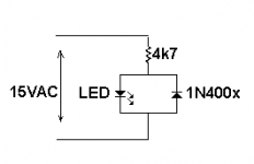
This circuit uses just two parts + the LED:
None of the values are critical.
The 4k7Ω resistor is a good value to start with. If more brightness is needed, just solder another 4k7 in parallel, piggyback style.
How many mA are needed?
With 4k7 the LED will have less than 1mA average current. Lowering the R to about 300 Ohms should give a little over 10 mA avg. But then the R is dissipating about a quarter Watt. Different color LEDs will behave slightly differently since they have different forward voltages. I don't know what color I was simulating.
Last edited:
I had it calculated at about 4mA peak current through the LED with the 4k7. That may be too low admittedly, which is why I mentioned paralleling another resistor. I think 300Ω is too low, in your circuit or mine. The differences with different colored LEDs appear minimal; the final resistor value is a question of how bright the OP wants the indicator.
BTW, when you wrote,
BTW, when you wrote,
you had it backwards. The diode-cap should connect to the LED anode, with the cathode to ground.From the diode-cap junction, run a series 330 Ohm resistor to the cathode of the LED. Connect the LED's anode to the ground end of the capacitor.
I had it calculated at about 4mA peak current through the LED with the 4k7. That may be too low admittedly, which is why I mentioned paralleling another resistor. I think 300Ω is too low, in your circuit or mine. The differences with different colored LEDs appear minimal; the final resistor value is a question of how bright the OP wants the indicator.
Yeah, I think 300 Ohms is too low, too. That's why I was pointing out the dissipation. That's why I was asking how much current was required. I seem to recall it usually being about 10 mA (average, not peak). But the newer high-brightness LEDs are supposedly bright-enough at 5 or 6 mA.
But I found this, too:
-----
As led forward voltages:
Red and green: 2 volts
Blue and white: 3.0 - 3.5 volts
Led current:
20mA will work for most regular leds.
Superbright leds can go from 30mA up to several amps.
-----
However, many "regular LEDs" are rated for 20 mA max. At any rate, we would want the minimum current that makes it bright-enough.
BTW, when you wrote,
<snipped>
you had it backwards. The diode-cap should connect to the LED anode, with the cathode to ground.
You would think that I could have just looked at my own schematic and gotten that right. 🙂
Yes. The technology has advanced to where it is difficult if not impossible to find the "low-current LEDs" that were around ~20 years ago.I seem to recall it usually being about 10 mA (average, not peak). But the newer high-brightness LEDs are supposedly bright-enough at 5 or 6 mA.
Using the peak AC voltage, the volt or two difference in colors wasn't significant in the few calculations I did for my circuit. Since there is some hysteresis involved in its on-off action, it's not easy for me to work out on paper or simulation.But I found this, too:
-----
As led forward voltages:
Red and green: 2 volts
Blue and white: 3.0 - 3.5 volts
Led current:
20mA will work for most regular leds.
Superbright leds can go from 30mA up to several amps.
-----
However, many "regular LEDs" are rated for 20 mA max. At any rate, we would want the minimum current that makes it bright-enough.
Those 30mA and up LEDs are useful for flashlights, signaling, and room lighting, but unless the datasheet says otherwise it's best to keep Iavg below 20mA with any LED.
Yep🙂You would think that I could have just looked at my own schematic and gotten that right. 🙂
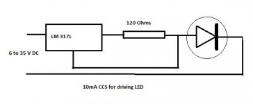
If you change the resistor to 100K, the circuit in post #3 can be wired to the mains.
Gajanan Phadte
Gajanan Phadte
Ok I decided to cheat
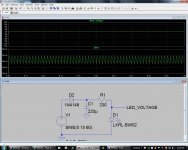
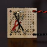
I realized that there are 12V LED diodes in blue and red 5mm. SO here is the cheat..... Radio Shack sells the LED in blue and red that I need in 12V with the resister built in. So instead of making a 5V supply from a 15VAC source, I went with a 12V 2A regulator. I copied a circuit from one I found on Google, the AC side goes into the bridge rectifier. The hot from the bridge rectifier goes through a fuse, across to the regulator in. Between the fuse and the regulator I have a 470 uf electrolytic 25v cap and then a .01 uf cap 50v ceramic. From the out of the regulator it goes to the 12+ lead with a .01uf cap between it and the lead. The ground of the rectifier goes to the ground of the electrolytic, the electrolytic negative goes across the negative of the first ceramic, then the ground of the regulator to a ceramic cap then to the negative DC lead.
I realized that there are 12V LED diodes in blue and red 5mm. SO here is the cheat..... Radio Shack sells the LED in blue and red that I need in 12V with the resister built in. So instead of making a 5V supply from a 15VAC source, I went with a 12V 2A regulator. I copied a circuit from one I found on Google, the AC side goes into the bridge rectifier. The hot from the bridge rectifier goes through a fuse, across to the regulator in. Between the fuse and the regulator I have a 470 uf electrolytic 25v cap and then a .01 uf cap 50v ceramic. From the out of the regulator it goes to the 12+ lead with a .01uf cap between it and the lead. The ground of the rectifier goes to the ground of the electrolytic, the electrolytic negative goes across the negative of the first ceramic, then the ground of the regulator to a ceramic cap then to the negative DC lead.
Attachments

Hi,
You do not need to rectified the Ac to Dc to light up the led. You can wire it as shown in post #3. Normally I used .005 ma when I need an led for indication. The higher the current the lower the life expectancy of the led. Wire it directly from the AC transformer wires. For 120AC I used a 40K resistor.
You do not need to rectified the Ac to Dc to light up the led. You can wire it as shown in post #3. Normally I used .005 ma when I need an led for indication. The higher the current the lower the life expectancy of the led. Wire it directly from the AC transformer wires. For 120AC I used a 40K resistor.
Cheat? There's more than one way to skin this cat. Yours is one of those ways.
Your circuit could be improved by taking into account what sort of supply the LED really needs.
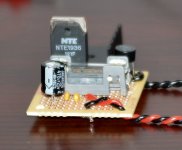
A 2A regulator is overkill; one of the 78L12 regs in a TO-92 package is all that is necessary. No heatsink required. And actually an LED doesn't even need a regulated voltage. There are better locations for the fuse also. Lastly, you're using the solder side of the PCB for the component side.
But you're DIY'ing & learning and that's the most important thing.
Your circuit could be improved by taking into account what sort of supply the LED really needs.
A 2A regulator is overkill; one of the 78L12 regs in a TO-92 package is all that is necessary. No heatsink required. And actually an LED doesn't even need a regulated voltage. There are better locations for the fuse also. Lastly, you're using the solder side of the PCB for the component side.
But you're DIY'ing & learning and that's the most important thing.
If I come directly off of the transformer, and 3 12V leds need to be on when individually switched, only two will be on at one time, would I still need only the one resister, diode and led?
Give up the 12V LEDs. They shouldn't be used in the post#3 circuit. If the AC is switched to each one, it doesn't matter how many you use until the total LED current used begins to adversely affect the main circuits.
If I come directly off of the transformer, and 3 12V leds need to be on when individually switched, only two will be on at one time, would I still need only the one resister, diode and led?
Does your board not have a rectifier circuit feeding + & - DC rails?
If so why not tap into the + rail and work out the resistor value needed for the LED.
If not, ignore this post 🙂
Davym... I have not settled on a USB/DAC and Tube Buffer yet. My idea was to make a USC/DAC and tuber buffer combination in one chassis. Neither board would be connected to the other. Both would have their own power supply, both would have their own inputs and out puts. The switch I am using is a lighted pushbutton that needs 12V to light the led, and I wanted to use a DPDT switch to cut the tube buffer in and out of the system, and there would be a blue and red LED indicating buffer in and buffer out. The DAC will use a stand alone momentary switch to chose between usb/optical/spdif and each has its own LED already if I use the board I am considering. My idea was to draw the voltage off of the 15VAC taps from the transformers so that when the power switch was thrown the power switch would light up and the LED for the tube buffer would light up. That's why I built the separate board.
What if I use a separate power led for the switch and forget a lighted switch.... I was thinking then of using a smaller bridge rectifier, a 79L05: 5V 100MA Negative Voltage Regulator TO-92 3 Pin, drop the fuse, and use the same caps and same circuit layout. The board does have a power rectifier circuit but other than pin outs I do not have a schematic.
LEDs are usually run from DC, which can be made by rectifying the AC and following the rectifier with a reservoir/smoothing capacitor. Optionally, that could be followed by a voltage regulator.
Gootee--you're recommending to effectively build a filtered power supply to light the LED. No need to do so. The LED will rectify the AC itself (after all, the "D" in LED is for diode). The resulting half-wave DC will turn the LED off for the non-conducting portion of the AC voltage, but that's OK--at 60 Hz, the eye will not even notice the flicker.
An easy approach: Grab a relatively large resistor (20k ought to do it), put it in series with the LED, and connect it to the 15 VAC. It probably will NOT light the LED--voltage drop across the resistor may be to high. Try a lower value resistor, until the LED lights. (Or better yet, use a pot [variable resistor] to find a suitable value to light the LED. (Don't go for "maximum brightness" on the LED, or you might exhaust your supply of LEDS....!) If you use the pot, light the LED, and replace the pot with a fixed value resistor.
It's BEST to use Sofaspud's suggested circuit (post #3). The second (non-LED) diode in his circuit protects the LED from the reverse voltage during the "negative" cycle of the AC supply........ Go for it........... Not much rocket science in this one..........
Last edited:
Don't forget the peak reverse voltage across the LED. Chances are very good that it is less than 15 volts. That's why the post #3 takes care off all that - peak reverse voltage across either diode and current limiting through each.You're done.
- Status
- Not open for further replies.
- Home
- Design & Build
- Construction Tips
- LED Power Light circuit