So I'm a big fan of blinking LED's and so on, so I was thinking it would be pretty cool to have a red and green (right and left) LED inside my preamp that would illuminate when a desired level was reached on the input. I searched around the web and couldn't really find what I was looking for so I thought I would come here for help. The closest I've found is this:
But it is stated to work more on speaker outputs (>1000mV), and what I want is something for line levels.
So, can someone help me with a simple simple circuit that could do what I want, preferably run on 12-15v and use 2n2222 or 2n5089 transistors? I dont want to use any IC's because I dont have them and would rather build this out of what I might have in my parts bin.
Thanks!
An externally hosted image should be here but it was not working when we last tested it.
But it is stated to work more on speaker outputs (>1000mV), and what I want is something for line levels.
So, can someone help me with a simple simple circuit that could do what I want, preferably run on 12-15v and use 2n2222 or 2n5089 transistors? I dont want to use any IC's because I dont have them and would rather build this out of what I might have in my parts bin.
Thanks!
Problems... thinking aloud here... and this is not an ideal circuit tbh
The circuit will only illuminate the LED when Vin exceeds the diode volt drop + the base emitter voltage of transistor. So that's nearly 1.5 volts to begin... no good.
You could add simple biasing to the transistor using either two resistors (if you calculate exactly) or a pot. That would allow the base to be brought to around 0.6volts (just below turn on voltage) and make the circuit much more sensitive.
Use a germanium diode (0.15 against 0.7v)
Omit the series diode altogether and add it B to E to protect against negative inputs.
Use a FET which would allow much higher impedances (less loading on audio circuit).
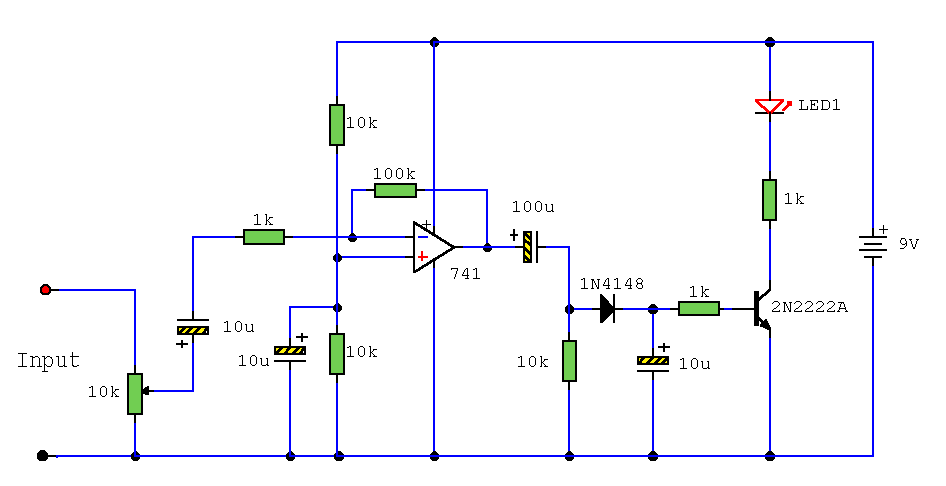
Or better still... use any opamp such as a 741
It's just like your original circuit with a -*100 amp in front of it. The opamp is just used as a linear gain stage.
This is more what I meant using an opamp as a precision rectifier,
Precision rectifier - Wikipedia, the free encyclopedia
but remember they are just building blocks as a way to a more complete circuit.
This is more what I meant using an opamp as a precision rectifier,
Precision rectifier - Wikipedia, the free encyclopedia
but remember they are just building blocks as a way to a more complete circuit.
- Status
- This old topic is closed. If you want to reopen this topic, contact a moderator using the "Report Post" button.
