Does anyone know where I could tie in a power indicator led into the leach amp?
I currently am not using a switch, just the power plug, but I'm not sure how I could get the desired voltage (other than a huge dropping resistor from the transformer or rectifier.)
Thanks,
Wes
I currently am not using a switch, just the power plug, but I'm not sure how I could get the desired voltage (other than a huge dropping resistor from the transformer or rectifier.)
Thanks,
Wes
hi wrl,
you can also use a neon lamp assembly, this is easier, but if you want an led, a series resitor of about 10k ohm at 2 or 5watt should do it, you can tie is off one of the rails...
you can also use a neon lamp assembly, this is easier, but if you want an led, a series resitor of about 10k ohm at 2 or 5watt should do it, you can tie is off one of the rails...
If you are using a toroidal trafo...wind abpout 10-20 turns around the trafo and get a measurement...adjust it till it's enough to light up ur LED...
led's don't some a lot of current (20ma tops usually). so you can figure out how big of a resistor you need, given the voltage source.
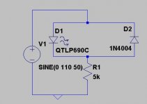
if the led is to be driven by an ac source, you may want to parallel a diode (4001 for example) in opposite polarily of the led so that it doesn't have to sustain large reverse voltage.
if the led is to be driven by an ac source, you may want to parallel a diode (4001 for example) in opposite polarily of the led so that it doesn't have to sustain large reverse voltage.
Hi wrl,
If you want to avoid a big hot power resistor, you could also use a capacitor to limit the current for an LED from the secondary of your transformer. Because an LED can not handle a big reverse voltage, you could use a small bridge rectifier and make the circuit as follows:
From one side of the secondary to the capacitor, from the other side of the capacitor to the bridge (AC connection), then the other AC connection to the other side of the secondary. The LED is then connected between the + of the bridge (anode) and the - of the bridge (cathode). The capacitor value depends on your secondary voltage, the mains frequency and the desired current through the LED. Start with 330nF, 100V. This is for 10mA at 60Hz and 80V secondary.
Steven
I used the same indication scheme as the A-75. Run a 10K resistor from each rail with the LED in the middle. It takes a while for the LED to go out after power off if you don't have bleeder resistors. adjust the size of the theresistance to get the bightness desired.
No, no, just connected to the secondary. If the capacitor fails the LED will blow. Take a capacitor with high enough voltage rating, just polyester will do.
Steven
Steven
...or you might want to consider winding a few turns arund the trafo and then running the LED from there...doesn't affect any thing whatsoever...other than extra stuff on ur trafo...
Thanks for the replies guys. Would it also be an option to apply the logic of these previous posts, but to put the diodes (or afformentioned circuits) between one end of the rectifier and ground, thus cutting the Voltage differential (and the resistor power rating) in half?
wrl said:Thanks for the replies guys. Would it also be an option to apply the logic of these previous posts, but to put the diodes (or afformentioned circuits) between one end of the rectifier and ground, thus cutting the Voltage differential (and the resistor power rating) in half?
if you put it on DC sources, you don't need the reversing diode. and the resistor can be much smaller. Something I prefer.
wrl said:...but to put the diodes (or afformentioned circuits) between one end of the rectifier and ground, thus cutting the Voltage differential (and the resistor power rating) in half?
That's where a capacitor has an advantage over the resistor; it will not dissipate since voltage and current is out of phase. And a higher AC voltage for this circuit allows for a smaller capacitance (although with a higher working voltage, so in effect it doesn't make a lot of difference what voltage is used). As long as you connect the circuit to an AC-source, such as the secondary of your power transformer, it is good to use both polarities of the sine wave and connect the LED in a diode bridge. The capacitor can be halved again in value for the same LED brightness. Furthermore the LED will flash at 100Hz (or 120Hz) which is not very visible. But if you only use a diode in antiparallel to the LED for reverse voltage protection, the LED will flash at 50Hz (or 60Hz). This can be annoying if your eyes pass the LED or if you move the LED; you will see it blink.
Steven
Keep your AC powered LED away from your amplifier's front end circuitry. Even more if you use a full bridge as suggested by Steven, as rectified sine waves have a nasty spectrum.
what's so wrong about ac powered leds? I mean if you use a reversing diode on it, there will be minimum rectification going on.
It's not the parts count or stuff or flashing LEDs..it's the fact that there's AC inside the amp makes me shudder...
The problem is if you're not talking about your own amplifier, you don't know where the LED and associated wiring will be placed, so you better recommend DC which will not radiate HF crap around.
Also, even 100 Hz can easily be recognized as not steady and I always found it annoying. The blinking LED grabs your attention whenever you move your head or eyes. It's the same with multiplexed displays. The problem disappears if you grow older.
Also, even 100 Hz can easily be recognized as not steady and I always found it annoying. The blinking LED grabs your attention whenever you move your head or eyes. It's the same with multiplexed displays. The problem disappears if you grow older.
- Status
- Not open for further replies.
- Home
- Amplifiers
- Solid State
- LED in leach amp