Knowing that the subject of Class A biasing is an important issue at this forum and at PassLabs, I conducted an experiment with my Class A amps, the Threshold SA/1's.
Before that I read some interesting stuff like the article 'Leaving Class A' from Nelson Pass about the benefits of enriching the output current of amps with a high bias current. Very convincing stuff indeed.
There is a thread on this forum called: Leaving Class A, and the article can be downloaded from the PassLabs website of course.
On the first page a list of current amplifier models is presented to show at which wattages the specific models shift from Class A to Class B.
The XA160.5 for instance has a nominal rating of 160 Watts, is biased with 3.2 Amps and leaves Class A at 328 Watts peak.
According to this article Push-pull amplifiers (like the XA160.5) operate in Class A mode at twice their biascurrent. So the figure of 328 Watts peak is obtained by: square(3.2 x 2) x 8 = 327.68.
The RMS value is half of that namely 160 Watts.
But their are different opinions how to establish the amount of Class A output for a given biascurrent.
In the Hifi News and Record Review of August 1991 the English reviewer Martin Colloms (He also reviewed equipment in Stereophile) states in a feature review about a Threshold SA3.9E amplifier that: "..semi-class-A mode, biased to a standing current of 2A. This allows for a fine class-A output of 16W. As in recent Krell reviews, I dispute Threshold's qualified claims for class-A operation."
Martin Colloms makes the following equation: square(2A x squareroot2/2) x 8 = 16 Watts instead of the claimed 60 Watts Class A for this particulary amp.
I know Martin Colloms is a major fan of Krell designs but that does not make his claim less credible.
So to test both claims I conducted an experiment with one of my SA/1's
According to the manufacturer the SA/1 should put 160 Watts Class A power into a eight Ohm load.
Setup:
- One 10A Variac (230 Volt line)
- An ammometer.
- Two Multimeters
- Two huge wirewound resistors (12 inch in length) each rated at 5 Ohms with several tappings for lower values.
I configured the resistors in series to get a 7 Ohm value.
I checked that with one of the mm's of course.
Connected one of the MM's in True RMS mode with the load for reading the outputvoltage and the other MM with one of the 1 Ohm emitterresistors in the amp.
Before that I measured twenty of them and they all lie within a 5% range.
The one I took measured 1 Ohm and closed the top with the leads connected to it as specified by Threshold's standard amplifier bias procedure.
I connected the 7 Ohm load to the outputconnectors switched the amp on and brought up the AC line to 220 Volts as the original AC Voltage for this amp.
I waited three hours before the AC power intake settled at 1.2A and the mm over the 1 Ohm resistor read 75 mV. That means a 3A bias (40 output devices times 0.075/1 = 3) which I have checked before at one of the railfuse connectors (2 x 1,5A).
The 75 mV and 3A settings are on spec for this amp.
Then I proceeded with playing a 1 kHz signal through it and level it with the volumeknob of my preamp.
First I turned up to the -10 dB setting on the panelmeter of my SA/1. The ammometer registrating the AC Voltage and the MM registrating the voltage over the emitterresistor showed their initial values. Then I turned up to -6dB and nothing happened either. Then at -3 dB both values increased just a little bit indicating that at that point the amp was leaving Class A.
At the 0 db setting both readings definitely increased significantly.
I went back to the - 3dB setting and measured over the 7 Ohm load a 16 Volts output.
This means with Ohm's Law an output current of 16/7 = 2.3 A, and an poweroutput of approx. 36 Watts.
Of course I was somewhat disappointed that my 160 Watt Class A amp could only boast 36 Watts of Class A power for real.
Has Martin Colloms a legitimate claim to dispute the Class A claims of Threshold and probably also the ones made by PassLabs?
He would state that the 3.2A standing bias for the PassLabs XA160.5 translates in a 40 Watt Class A output. My experiment would confirm that specification it seems.
Other thoughts?
By the way; The amp could crank out 40 Volts easily though at 8 or 4 Ohms. At those readings you could clearly hear the resistors producing the 1 kHz feeding signal.
Last edited:
If your amplifier shows a 3 amp bias, then it will enter
cutoff at 6 amps peak, which into 8 ohms is 6 X 6 X 8 =
288 watts peak which becomes 144 watts rms with a
sine wave. That you measure slightly more draw at -3dB
is not particularly important.
😎
cutoff at 6 amps peak, which into 8 ohms is 6 X 6 X 8 =
288 watts peak which becomes 144 watts rms with a
sine wave. That you measure slightly more draw at -3dB
is not particularly important.
😎
Last edited:
Brian, if you measured 75 mV over the 1 ohm, the standing current is only 75mV/1ohm *20 = 1.5A not 3A since the 40 output devices are splitted into 20 on the positive and 20 on the negative power supply rail. This explains why in your experiment your amp is leaving class A at about 36 W.
Martin Colloms' calculation is only true for single ended design while Nelson Pass' calculation is true for push pull design.
HTH
Martin Colloms' calculation is only true for single ended design while Nelson Pass' calculation is true for push pull design.
HTH
while Papa is known well as notoriously not caring for numbers and specs ( at least publicly and in his own Service Manuals - that all probably because all job is already done ,when SM must be made) ...... I also have slight impression that he made few more amps than Mr. Colloms .....
in any case - conducting your own tests is positive thinking in work ......
edit:
everything is in perspective ....... Papa mentioned one crucial word "cutoff" ;
for him - that's where amp leaves A and goes to B
AB is probably .......... who cares
in any case - conducting your own tests is positive thinking in work ......
edit:
everything is in perspective ....... Papa mentioned one crucial word "cutoff" ;
for him - that's where amp leaves A and goes to B
AB is probably .......... who cares
Last edited:
Gathering from your replies it's only a matter of definition?
I know the difference between a complementary design (Push Pull) with PNP and NPN output devices sharing the load and single-ended ones. I know what cutoff and saturation means.
The meterreadings at the front of the amp are not really important here. I believe those Modutecs are calibrated for peaklevels.
I also know that the 75 mV reading at the emitterresistors counts for 1.5 Amps at the Positive railvoltage (PNP devices) and another 1.5 Amps at the Negative railvoltage (NPN devices). That constitutes 3A bias in total for one channel.
When the PassLabs XA160.5 Class A Push Pull design is specified to have a 3.2A bias per channel does the mean, along the lines of Jacky's reply:
1. That this only counts for the negative or positive supply;
2. or both of them (2 x 1.6)?
If the first case is is true I should increase my bias for the SA/1 to a reading of 160 mV to get a 3.2A bias each for the Negative and Positive powersupply, 6.4A in total for having a 160 Watts RMS Push Pull Class A Poweramp at eight Ohms.
In the second case the XA160.5 would be a 80 Watts RMS Class A poweramp.
So at the moment my SA/1 is underbiased to be a 160 Watts Class A amp.
With 3 Amps bias in total in my case can sombody tell me then what is happening at the measured outputvoltage of 16 Volts I over the 7 Ohms dummyload when from that moment on the voltage over the emitterresistor is steadily rising (> 75 mV) as the intake of AC Power is?
What shift is going on from that moment?
I interpreted as that the particular powertransistor stops amplifying the full sine wave and from that point onwards only increases the negative or positive portion of the cycle depending if it is a NPN or PNP device.
But that is then probably not the point the amp seizes to be a Class A design?
Can somebody explain to me at what point the amp shifts from Class A to Class B?
....
I also know that the 75 mV reading at the emitterresistors counts for 1.5 Amps at the Positive railvoltage (PNP devices) and another 1.5 Amps at the Negative railvoltage (NPN devices). That constitutes 3A bias in total for one channel.
..........
nope - bias/shmias is sum of current going from positive to negative side of PSU; so , in this case you have just 1A5 of Iq
ground is just reference point for amplifier ..... well , sort of .
amplifier doesn't care for ground , energetic wise - in steady condition , without signal .
so - that's just engineer's choice where other side of loudspeaker will be connected ..... example : in bridged amps loudspeaker isn't connected in any way or means to gnd ...... but to just opposite potential point , looking from one amp/half hot output to another amp/half output
leaving class A point - I'm pretty sure it's somewhere where one side ( either positve or negative ) is choked/closed/non-conductive ........
cutoff .
(first morning coffee still not finished , English isn't my native ..... just few reasons why I didn't/can't write all this in more clearer way )
nope - bias/shmias is sum of current going from positive to negative side of PSU; so , in this case you have just 1A5 of Iq
So that means 1.5A quiescent current.
According to Nelson Pass that would mean for a PushPull design:
square(2 x 1.5) times 8 = 72 Watts Class A peak, 36 Watts RMS?
To get to 144 Watts Class A RMS one would need a double amount of Iq:
square(2 x 3) times 8 = 288 Watts Class A peak and 144 Watts RMS.
I wonder how hot my SA/1 becomes when I turn up the bias to 150 mV on the 1 Ohm emitterresistors to get the 3A iq.
So when I measure 3A at the negative railfuse holder (fuse removed of course ;-)) then it should be 144 Watts Class A RMS?
It now idles at 43 degrees Celcius and according to the Threshold Standard Biasing Procedure of 1989 a SA/1 'non optical bias' version should idle at 42 degrees Celcius. My roomtemperature is a normal 20 degrees by the way.
Know what you mean. Apart from the coffeine, tt's a major disadvantage in this technical world if you're not a native English speaker.(first morning coffee still not finished , English isn't my native ..... just few reasons why I didn't/can't write all this in more clearer way )
Last edited:
like someone said - "don't use force ..... use bigger hammer"
seems that your Treshold is well biased ; according to Papa - it's hardly possible that you're hearing "BANG" in moment when amp is coming to B class .
your intellectual side can be satisfied with that math above ...... and I hope that your speakers are satisfied with Treshold ...... doesn't matter which type of Watts are coming out
I think the clear indicator is that your amps are underbiased,
since you are drawing 1.2A*220V out of the wall.
If you count the number of devices along the top of the
heat sink on both sides, you should divide 3.16 by that
number and that will tell you the bias figure you probably
want.
At the same time you should check the heat sink temperature
so that it doesn't exceed about 55 deg C. over the course of
a couple hours.
😎
I think the clear indicator is that your amps are underbiased,
since you are drawing 1.2A*220V out of the wall.
If you count the number of devices along the top of the
heat sink on both sides, you should divide 3.16 by that
number and that will tell you the bias figure you probably
want.
At the same time you should check the heat sink temperature
so that it doesn't exceed about 55 deg C. over the course of
a couple hours.
😎
Two transistors on the top rows are the Stasis devices does that make any difference? So 18 transistors are the currentdumping devices.
Okay I know what you mean. 3.16 Amps must be shared by 20 devices meaning 0.158 Amps per device with a 1 Ohm emitterresitor means 0.158 mV.
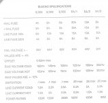
I used the attached specifications from Threshold self were in a hot state on a 120 Volts line the SA/1 should have a AC intake of 2.2A. That means 1.2A for a 220 Volts line I reckon.
I thinks it's to conservative probably.
I'll try your settings and hope the thermistors on the Stasis devices will allow that.
Attachments
like someone said - "don't use force ..... use bigger hammer"
seems that your Treshold is well biased ; according to Papa - it's hardly possible that you're hearing "BANG" in moment when amp is coming to B class .
your intellectual side can be satisfied with that math above ...... and I hope that your speakers are satisfied with Treshold ...... doesn't matter which type of Watts are coming out
I know that the Class A in itself is not the only criteria for having a good sounding amp.
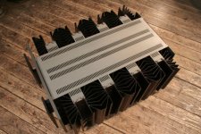
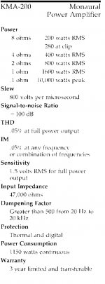
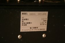
I've had a pair of Krell KMA-200 series II's that idled at a 1150 Watts intake from the line and had to be cooled down by two fans at each channel.
Later Krell came up with a package called the KRS-200 (1050 Watts AC intake) that was convection cooled but needed a huge chassis to cool it down enough. My SA/1 fits in three times in that design.
I found the Rowlands 7 and Threshold SA/1 more musically satisfactory the the KMA-200's. But I wondered how Threshold could crank out almost the same Class A power (160 Watts vs 200 Watts) with a much smaller chassis and convectionsurface.
Wiil attach a pic so you can see it for yourself
It's that a lot of effort is made by PassLabs to stress the importance of heavily biased simple circuits. I've seen a dozens of graphs relating to the benefits of it at their published articles, and I tend to take them seriously not as a market hype.
Attachments
Those AC current figures are very likely taken with an
averaging AC meter. As you are reading rms, you should get
a number about 40% higher. You should expect to see in
excess of 320 watts draw, and as a rough approximation
this would be about 1.4 Amps at 240V. By design it is likely
to draw the same current at 220V.
The chart you show looks low with regard to bias voltages.
You will want the 160 mV figures you calculate.
Historically I have suggested that you set the bias so that
the sinks run at 55 deg C, which is as hot as I consider
reliable. I would be surprised if the idle current of the
KMA200 was as high as 1150 watts.
😎
The thermistors at the Stasis section that keep the temperature in check to prevent a thermal runaway are working against a easy setting of the bias.
These devices push back the Iq every time I turn the bias up and close the top. I managed 100 mV on both amps 1.7 A from a 220 Volts line and 24 Volts output with a 7.5 Ohm dummy load before the Multimeter value at the emitter was creeping up. That's 80 Watts RMS and the panelmeter that is calibrated for peaklevels is at it's 0 dB setting.
When I started to increase the bias to 160 mV for the first time, the amp was only 43 degrees Celcius then, I indeed got the 34 Volts corresponding with a 160 Watts Class A RMS value. So I must admit that this value is reachable within the temperature-envelope Nelson Pass supplied (54 degrees Celcius max).
So to my opinion/experiment - I've been enlighted - it's:
Pass - Colloms 1-0 on biasing matters!
I think with the designated Series II Thresholds (which I have) some measures were taken to get a faster startup with a increased biascurrent in the beginning, but thermistors were added to prevent a thermal runaway. With the optical bias versions all these problems were probably solved and these amps could run hotter because the biascircuit was (more) independent from other parameters. The Threshold Standard Biasing Procedure (posted on this forum already) from 1991 stipulates that the non-optical versions should run at an idlingtemperature of 42 degrees Celcius and the optical biasversions at 49 degrees.
With the 42 degrees setting even a 80 Watts RMS setting is unobtainable. I managed only 34 Watts Class A at that temperature.
I assume that the 49 degrees I have now after hours of idling is still a safe value with my Series II amp?
........
So to my opinion/experiment - I've been enlighted - it's:
Pass - Colloms 1-0 on biasing matters!
......
well ....... surprise !
.......
I assume that the 49 degrees I have now after hours of idling is still a safe value with my Series II amp?
......
Historically I have suggested that you set the bias so that
the sinks run at 55 deg C, which is as hot as I consider
reliable. .........
😎
idle current of the KMA200
KMA200 does 580W idle, is per channel, 1160W the stereo set.
(the MDA500 idled at 600W each)
Attachments
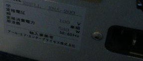
I did not make any photo's from the back them when I had them some 18 years ago but I had a huge 2.5 kVA Toroid, 6 Mallory 40.000 uF capacitors and two "tunnels" with eight powertransistors in each of them at the rear with fans attached to them blowing upwards on the Series II. Before that I had a KSA-100 with fans blowing downwards against the natural convection flow.KMA200 does 580W idle, is per channel, 1160W the stereo set.
The KRS-200 also rated 200 Watts Class A at eight Ohms had a 1050 Watts intake.
The KRS-200 was the first design by Krell to get a 200 Watts Class A poweramp in a natural convection cooled chassis.
Attachments
Hi Zen Mod
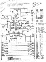
Yse I read this advise by Nelson Pass but I also have this Bias service manual were 42 degrees Celcius for a non optical bias version of the SA/1 is recommended by the manufacturer itself.
I also supplied a Schematic of the Series II
Originally Posted by Nelson Pass
......
Historically I have suggested that you set the bias so that
the sinks run at 55 deg C, which is as hot as I consider
reliable. .........
Yse I read this advise by Nelson Pass but I also have this Bias service manual were 42 degrees Celcius for a non optical bias version of the SA/1 is recommended by the manufacturer itself.
I also supplied a Schematic of the Series II
Attachments
two "tunnels" with eight powertransistors in each of them at the rear with fans attached
1150W divided by 2*8 output devices is 72W dissipation per power transistor.
Even with modern high performance heatsinks and high volume fans the temperature of the output devices in a KMA-200II would be too elevated, and Krell didn't have access to such heatsinks at the time.
The KRS has/had 8 of the typical Krell design heatsinks, each of them carrying half a dozen output devices, with a driver for each heatsink assembly.
A single of those heatsink packages handles +130W dissipation easily without having the dies of the output devices at a non-conform temperature.
The Reference Standard series differs, they ran Full Class A in 4 Ohm, corresponds to 75V rails and 7 Amp bias.
(the KRS-200 was part of the Krell works that drove the Martin Logan Statement E1 on it's world tour, i attended the Paris display)
Hi Zen Mod
Yse I read this advise by Nelson Pass but I also have this Bias service manual were 42 degrees Celcius for a non optical bias version of the SA/1 is recommended by the manufacturer itself.
I also supplied a Schematic of the Series II
knowing that Pass designed them , I'll not hesitate to do what he said .
1150W divided by 2*8 output devices is 72W dissipation per power transistor.
Even with modern high performance heatsinks and high volume fans the temperature of the output devices in a KMA-200II would be too elevated, and Krell didn't have access to such heatsinks at the time.
I think you're right there. They probably quote a AC intake for a pair.
It seemed so strange to me that one manufacturer needed three times the powerdissipation for almost the same Class A output.
The KRS has/had 8 of the typical Krell design heatsinks, each of them carrying half a dozen output devices, with a driver for each heatsink assembly.
A single of those heatsink packages handles +130W dissipation easily without having the dies of the output devices at a non-conform temperature.
The Reference Standard series differs, they ran Full Class A in 4 Ohm, corresponds to 75V rails and 7 Amp bias.
(the KRS-200 was part of the Krell works that drove the Martin Logan Statement E1 on it's world tour, i attended the Paris display)
Their construction (not their design) reminded me of the Levinson ML-2/No. 20 series.
But D'Agostino was determined to beat Levinson in every parameter so their reference line had to be bigger of course.
I think the ML-2 could boast even Class A at their 2 Ohms rating Off course that design had only a 17 Volts (27 Volts regulator output) max output but in every possible load.
In basically the same chassis a No. 20 ran 100 Watts Class A at 8 Ohms but 50 at 4, 25 at 2....
It took me a long time to be honest that you can have a load of different amps by just changing the railvoltage and/or have them in bridged configuration with exactly the same hardware.
I'm happy now with my Thresholds. They purr and with this kind of weather the central heatingsystem does not kick in at all seriously.
- Status
- Not open for further replies.
- Home
- Amplifiers
- Pass Labs
- Leaving Class A? Martin Colloms vs Nelson Pass