Hello,
Not long ago I was living with my parents and I had access to a drills and lots of parts and most of all: a backyard. Now I live in an apartment with my girlfriend, a scope and a soldering station. I can not build as many prototypes as I'd like... So I thought I'd give LTSpice a try. As with any other tool, if I know how to use it correctly I'm sure it can save me time and money.
My current project is a 3-Way active speaker (well, 2 speakers actually). The signal will first go through an active cross-over then to the amps.
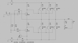
In order to save space I'd like to use the opamps on the cross-over to bring the single to +/- 18v and then straight to the output stage drivers; (see attached file)
V3 is the single and the output of U1 would be the output of the active cross-over. I'm looking at this and it all seems too simple: there must be something that won't work in real-life... (I can't believe it can be that simple). PCB Layout will influence a lot but I'm sure that's not the only thing LTSpice doesn't simulate; any input ?
Thanks !
Not long ago I was living with my parents and I had access to a drills and lots of parts and most of all: a backyard. Now I live in an apartment with my girlfriend, a scope and a soldering station. I can not build as many prototypes as I'd like... So I thought I'd give LTSpice a try. As with any other tool, if I know how to use it correctly I'm sure it can save me time and money.
My current project is a 3-Way active speaker (well, 2 speakers actually). The signal will first go through an active cross-over then to the amps.
In order to save space I'd like to use the opamps on the cross-over to bring the single to +/- 18v and then straight to the output stage drivers; (see attached file)
V3 is the single and the output of U1 would be the output of the active cross-over. I'm looking at this and it all seems too simple: there must be something that won't work in real-life... (I can't believe it can be that simple). PCB Layout will influence a lot but I'm sure that's not the only thing LTSpice doesn't simulate; any input ?
Thanks !
Attachments
I just had a short look at your circuit; looks ok basically.
What opamp do you use? You seem to use only very little feedback which makes me curious as opamps usually have very high open loop gain.
Have fun, Hannes
What opamp do you use? You seem to use only very little feedback which makes me curious as opamps usually have very high open loop gain.
Have fun, Hannes
h_a said:I just had a short look at your circuit; looks ok basically.
What opamp do you use? You seem to use only very little feedback which makes me curious as opamps usually have very high open loop gain.
Have fun, Hannes
Actually, the feedback will be connected to the emitter of Q1 and the base of Q1 will pass thought a 2.7k resistor and to the output of the crossover which is actually a PGA2320 (Short current is 75mA) I think I might need a buffer there... what do you think ?
- Status
- Not open for further replies.