Hi all
Solid state is not really my thing but I inherited an old leak Stereo 70 I would like to get going. It was running but I couldn't stabilise the quiescent current which kept rising even after warm up. I was working through replacing parts on the power and pre amp boards when I stupidly put a new trimmer in without checking the setting. One of the 10r resistors blew and a couple of ominous cracks which I think were transistors.
I've now changed output transistors and driver transistors on the power amp boards but I'm still not getting current. I powered up on the lamp limiter and no smoke was let out!
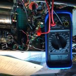
Checking dc voltages on the output transistors I get:
T11L collector 34v emitter and base 0v
T10L collector 65.5v emitter and base 34v
T11R collector 32.4 v emitter and base 32.4v
T10R collector 65.4v emitter and base 0v
The 75v rail on the schematic is just under 10v low but can anyone suggest a good place to look as to why I'm not getting joy on T11L and T10R? I've replaced all capacitors on the pre and power amp boards and any obviously out of range resistors. The circuit diagram has a couple of diodes per channel D1 and D2r but embarrassingly I can find them in the amp itself.
The circuit is here:
http://44bx.com/leak/Leak/Circuits/cctStereo70.gif
Feel free to assume a level of retardation in my knowledge!
Regards
Mike
Solid state is not really my thing but I inherited an old leak Stereo 70 I would like to get going. It was running but I couldn't stabilise the quiescent current which kept rising even after warm up. I was working through replacing parts on the power and pre amp boards when I stupidly put a new trimmer in without checking the setting. One of the 10r resistors blew and a couple of ominous cracks which I think were transistors.
I've now changed output transistors and driver transistors on the power amp boards but I'm still not getting current. I powered up on the lamp limiter and no smoke was let out!
Checking dc voltages on the output transistors I get:
T11L collector 34v emitter and base 0v
T10L collector 65.5v emitter and base 34v
T11R collector 32.4 v emitter and base 32.4v
T10R collector 65.4v emitter and base 0v
The 75v rail on the schematic is just under 10v low but can anyone suggest a good place to look as to why I'm not getting joy on T11L and T10R? I've replaced all capacitors on the pre and power amp boards and any obviously out of range resistors. The circuit diagram has a couple of diodes per channel D1 and D2r but embarrassingly I can find them in the amp itself.
The circuit is here:
http://44bx.com/leak/Leak/Circuits/cctStereo70.gif
Feel free to assume a level of retardation in my knowledge!
Regards
Mike
Check the 1R emitter resistors and replace the bias presets as they go open circuit or drift around causing uncontrolled excess bias. Ensure the double diodes are thermally connected to the output transistor heat sink.
If you open the link for setting the bias current, place a 1R resistor in place to check the quiescent current adjustment, not forgetting of course to put the link back before driving loudspeakers.
Its a classic text book amplifier.
Check all the resistors below 1k in that area (such as the 1 ohms, the 10 ohm s and the 220 ohms. Driver transistors are almost certainly popped if the outputs failed. T7 may have taken a hit as well.
Your voltage readings are a bit confusing. T11 emitter is grounded and so should be at zero volts. The base of T11 should always be at around 0.6 volts DC. If there is really voltage on the transistor emitter then the print or wiring is open.
Thanks for the pointers. I will dig back in. The DC voltages were as measured relative to chassis ground. I haven't physically located the double diode in the chassis but will remove one of the main smoothing cans which blocks access to the bottom of the heat sink area. I was hoping this would be a quick one but it is turning into one of those jobs!
Ok I re opened the patient and found the missing set of in3754 diode pairs. They were lurking behind a tag strip butted up to the "heat sink" aka thin piece of steel. Having set my multimeter to diode which I've never used before I get OL. I'm assuming this is bad and replace?
Thanks
Mike
Thanks
Mike
Attachments
The meter should register a reading when connected one way around across a diode and give 'no' reading when connected the other way. OL means 'open' or no continuity. The other way around and you should see something like 0.600 which would be 600 millivolts... approximately the forward voltage of a diode. If it read low (less than around .500) then it could be faulty.
You can only check things like diodes when they are disconnected from the rest of the circuit.
You can only check things like diodes when they are disconnected from the rest of the circuit.
There are 6 transistors in that power stage.
If you measure the voltages of all and record them then we would have a much better idea what was going on.
You can copy and paste this and record your results.
TR6.
C=
B=
E=
TR7.
C=
B=
E=
TR8.
C=
B=
E=
TR9.
C=
B=
E=
TR10.
C=
B=
E=
TR11
C=
B=
E=
If you measure the voltages of all and record them then we would have a much better idea what was going on.
You can copy and paste this and record your results.
TR6.
C=
B=
E=
TR7.
C=
B=
E=
TR8.
C=
B=
E=
TR9.
C=
B=
E=
TR10.
C=
B=
E=
TR11
C=
B=
E=
Thanks Mooly
Ok I whipped one out of circuit and with the meter on diode I get .003 measured in both directions. From your previous description these are fried? If so any idea on a suitable modern replacement. Happy to do voltages once it's back together.
Thanks again
Mike
Ok I whipped one out of circuit and with the meter on diode I get .003 measured in both directions. From your previous description these are fried? If so any idea on a suitable modern replacement. Happy to do voltages once it's back together.
Thanks again
Mike
Yes, it would appear they are faulty (almost short) with those readings. Very hard to make out in a picture... I take it they clamp to the heatsink. Are they glass ?
The good news is that they are silicon diodes and should be OK to replace with something like a 1N4002 or similar. You need something physically similar at any rate. The 1N4148 would also be OK electrically but might be to small. You'll have to check the approximate sizes 😉
With those diodes short, the amplifier should still all work but would have near zero bias current and so develop a little crossover distortion. So if the amp isn't actually working and producing audio then you have another problem as well.
All the transistor voltage readings would still be valid even with those diodes shorted so you can still proceed even with the shorted diodes.
I'll look in again tomorrow. Good luck.
One thing... before we condemn them totally you should check them with one wire going to them unsoldered, so that they are not connected to the rest of the circuit. Residual voltage (charged up caps) can give misleading readings.
They do read that low that they do sound to be zapped but always best to be sure. Being zapped also means the current that did the damage must have flowed through the preset trimmer resistor, so that could be suspect as well.
Another pretty definitive test is to measure the voltage across each diode when the amp is on. It should be at least 600 millivolts and less than around 750 millivolts.
Wierd looking schematic symbol for NPN transistors.
That said,what I do a lot of times in basic solid state amps with silicon transistors is to measure base to emitter turn on command and that usually reads in the area of .55vdc to .7vdc..That tells you that transistor is turning on and is probably good. Since you have a low B+ rail,I would do this because if you have one transistor and associated components reading .3 to .4vdc,that would be a good place to start looking for the problem. You also have the power supply input filter caps that can drop the rail but like the other posters have said,the bias pots a good bet as open and even short at times.
That said,what I do a lot of times in basic solid state amps with silicon transistors is to measure base to emitter turn on command and that usually reads in the area of .55vdc to .7vdc..That tells you that transistor is turning on and is probably good. Since you have a low B+ rail,I would do this because if you have one transistor and associated components reading .3 to .4vdc,that would be a good place to start looking for the problem. You also have the power supply input filter caps that can drop the rail but like the other posters have said,the bias pots a good bet as open and even short at times.
Two 1N400* is a good substitute, they have a larger area to detect heat. Just as a matter of interest for waam68, semiconductors change conduction with temperature. A diode when warm, or indeed the junction between base and emitter of a transistor, reduces in voltage drop, (the result is a higher quiescent current) so to help compensate for current drain, (base and emitter needs less voltage across it to turn the transistor on so it turns on too much), {thermal runaway}, we use the falling voltage drop of two diodes to compensate for the falling junction voltage requirement. That helps to keep the runaway to a minimum. Hope that you will find that explanation useful.
Hi guys
Yes many thanks this is all useful. Unfortunately I have no background in electronics and usually build very simple single ended valve/tube circuits so am basically self taught to build these simple circuits from messing with kits and simple scratch build from existing schematics. There are usually problems but I mostly get there in the end if not always by the simplest route. I always learn something so please excuse my lack of knowledge. For me this IS a relatively complex circuit. As the amp is in bits I will replace the diodes and take it from there on the lamp limiter and report back. My motivation for this project is I have a pair of original leak sandwich 15 ohm 2 way speakers that I drive with a Morrison micro 2A3 amp (sounds really great) and I thought it would be interesting to compare to a contemporary ss amp. Ps to recap I have already replaced all output and driver transistors (after I "blew it up").
Regards
Mike
Last edited:
That sounds like a plan.
I would at least check the bias preset is OK on your meter. Its resistance should vary from near zero up to 200 ohms or so. With the diodes unhooked you can just place your meter across the preset and test it.
When you power the amp up, use the bulb tester as you have already mentioned and also ensure you start with the bias preset on minimum resistance as that will give minimum bias current.
The rails will be a little lower than normal because of the bulb.
Now fixed
Hi all
Just a quick update to say thanks for all the help. It's taken me a while to track down and sort the various problems. Thanks Jon Snell the IN400 diodes worked fine. In the end I cleaned all pots and switches, replaced driver transistors, output transistors, all electrolytic caps and the tubular carbon resistors many of which had gone high and lastly re set the q current. It's working fine now with no hum and sounds v good to me. My last problems were no bass on one speaker....turned out a piece of component lead I'd snipped off had got wedged and shorted a transistor on the preamp board and a hum on the phono input turned out to be my SUT being too close to the power transformer. I could have built an amp in less time than its taken me to do this one...de soldering from old PCB's is a pain. Ps every time I upload a pic from my iPad on this board it inverts?
Mike
Attachments
- Status
- Not open for further replies.
- Home
- Amplifiers
- Solid State
- Leak stereo 70 not working