All that it is necessary to do to the crossover you are refurbishing is to replace the ageing ELCAP bipolar electrolytic capacitors with modern equivalents.
For example, you may replace a 25 uF ELCAP with a modern standard value of 22 uF as the tolerance of ELCAPS wasn't tight in the first place.
If you are fussy, wire a 3.0 uF in parallel with a 22 uF to give 25 uF. https://wilmslowaudio.co.uk/mundorf-electrolytic-ecap-capacitors
The inductors and resistors can be left as is which will help ensure the originally intended sound quality.
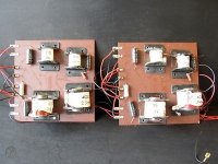
I found this image and we can make out the L values.
2 X 0.2mh
1x 2mh
1 x 2.5mh
25, 25, 4.7uf caps

2 X 0.2mh
1x 2mh
1 x 2.5mh
25, 25, 4.7uf caps

Thanks all - mine have a 6microFarad cap instead of the 4.7 in jimk's picture but they look original. I'd still be interested to see the circuit diagram if anyone has one.
Draw it out - there's hardly anything to it - piece of paper and a pencil, job done.Thanks all - mine have a 6microFarad cap instead of the 4.7 in jimk's picture but they look original. I'd still be interested to see the circuit diagram if anyone has one.
I'm with Nigel.
Since you have physical access to the front and rear of the crossover board you are in a good position to try roughing out the circuit diagram for yourself.
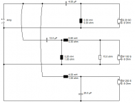
As a guide, the layout will be similar to that of the attached Wharfedale Linton 3XP crossover (courtesy of member system7).
(From top to bottom: tweeter; midrange; woofer.)
Since you have physical access to the front and rear of the crossover board you are in a good position to try roughing out the circuit diagram for yourself.
As a guide, the layout will be similar to that of the attached Wharfedale Linton 3XP crossover (courtesy of member system7).
(From top to bottom: tweeter; midrange; woofer.)
Attachments
Thanks boys ... you are of course right but following the printed circuit as it squiggles around like a tray of snakes and switching my attention between the components on the front and the blobs of solder on the back makes me go cross-eyed and dizzy ;-)
You can imagine how tricky it would be to do it from photographs! 😀
Simply replace the capacitors - the audible difference may astound you.
Simply replace the capacitors - the audible difference may astound you.
I have replaced the capacitors with ALCAP equivalents - same values but rated at 100V instead of 50V - and the speakers now sound as good as new - thanks to all
- Home
- Loudspeakers
- Multi-Way
- Leak 2030 crossover circuit diagram