Whats a good program to do a circuit diagram in?
IT must be some kind of program that has the necessary symbols you guys use?
Its easy made as i just copy the superamp and then add 2 pars of output devices and the necessary extra resistors that will be needed, 4 i think.
IT must be some kind of program that has the necessary symbols you guys use?
Its easy made as i just copy the superamp and then add 2 pars of output devices and the necessary extra resistors that will be needed, 4 i think.
You could use LTspice and print out via a PDF "printer". As a side effect you could simulate your design.
If you download the leach amplifier simulation from the leach site that would give you the models for the transistors.
Yes, 4 extra transistors would be needed for one extra "bank"
If you download the leach amplifier simulation from the leach site that would give you the models for the transistors.
Yes, 4 extra transistors would be needed for one extra "bank"
My fiances pc has win 8 so LTSpice wont work.. either does the circuit program. Win 8, a bit annoying... someone know some program that works with win 8?
Isn´t people interested in high power versions of a well regarded amp?
I think there is 🙂
but 100W-ish amps are most common on this forum.
My fiances pc has win 8 so LTSpice wont work.. either does the circuit program. Win 8, a bit annoying... someone know some program that works with win 8?
Really strange... can you do an emulation mode?
check the ltspice yahoo group for a workaround. Most ppl here use ltspice
Another good free program (with nodes limits) is simetrix, check the free/intro version, maybe it will install on w8.
computers and me equals trouble as i am not interested in them and because of that, my skills are very limited. Don´t know how i do an emulation mode?
I would like to create this amp. But, i am not shure on how to go on, just copy the scheme of the superamp, then put 4 pairs of out devices in the same manner as PRof Leach did when he made the superamp from the original leach?
Dont know.. IT is cascoded, do i need to cascode again then or what?
I am a novice, yes. But i also know that some of you know how i should do to get it to work. Please share your experience with me.
computers and me equals trouble as i am not interested in them and because of that, my skills are very limited. Don´t know how i do an emulation mode?
I dont use win8 (because I dont like it), so I cannot help. i remember that for instance in vista/w7 you could do an XP emulation mode when installing or running a program.
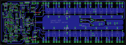
The pcb that Rudi posted looks very good and also the devices used, I would follow that 🙂
You will find the author (the schematics as well?) of this amplifier here:
Zosilòovaè 700W
Best regards - Rudi_Ratlos
Zosilòovaè 700W
Best regards - Rudi_Ratlos
Hi Guys
When the Double Barrel amp was designed, there were not the range of high-quality symmetric high-voltage power transistors that we have today. At +/-90V there is no real need to cascode, although it is a traditional way to avoid secondary breakdown if the applied Vce is much lower than the full rating.
Tony suggested the MJ21193/94 pair, which is an industry standard used in the highest quality amps available today. The MJL1302A/3281A are also fine, as are all of their equivalents.
To avoid cascoding, there are two options. The first is simply to expand the output stage "sideways" with twice as many paralleled pairs. This increases the load on the driver s, so those should be changed to a higher rated type. The MJE13034/35 pair is the new kid on the block and again appears in the best amps.
If you wanted to be adventurous, driver distortion can be reduced compared to the doubled output stage by expanding "vertically" but not as a cascode. The second approach is to use the Quad Complimentary output stage as Bryston does, but not wired for gain. It is a simple matter to make QC-EF by beginning with the standard EF stage and adding collector resistors to the drivers. Then add PNP outputs driven by the collector of the NPN driver, with the output collectors tied to the output node. NPNs are added on the negative circuit half in a similar fashion. The load is now driven by emitters and collectors on both halves of the wave. Bryston's actual output circuit is more like a QC-CFP overall, allowing significant reduction of openloop THD.
In either approach, the doubled output stage not cascoded has the same number of output devices as the cascoded circuit, so dissipation is shared in a similar way. The QC keeps driver THD from rising compared to the normal EF expansion.
In all cases, emitter resistors (and same-value Rs in the collectors of the QC collector outputs) provide a means to monitor all device currents for protection.
Leach's circuit is still an industry standard for good reason. The benefits of complimentary circuitry are plentiful: the potential for distortion reduction is high; and more importantly, attaining a benign THD profile is easy.
Cascodes waste voltage headroom but can increase bandwidth, making them prone to oscillation. Leach added the base-stops to cure this ill. Paralleling many devices can also lead to oscillation problems, which are cured the same way. Layout is key to either circuit being stable.
Have fun
Kevin O'Connor
Last edited:
There has been from time to time expressions by the moderators about building higher voltage amplifiers. This one would be in that category.
Would at least one of the moderators acknowledge this and give a go ahead before time and thought are applied here and prevent false hopes from being raised by those that want to undergo the cost and inherent dangers of amps of this ilk.
If the go ahead is given I hope that Alex will bless the situation with his audacious expertise. 😀
Forward...
I think the main concern with high voltage designs are the direct connection to AC switching supplies; the lack of an isolation transformer leads to some real dangerous conditions if very strict double-insulation practices are not followed. That's why I built an isolation transformer into my big bench variac; it's center-tapped so I can use it as a quick and easy dual polarity power supply for large amplifier testing.
Tubes invariably involve hazardous voltages--at much higher voltages.
Tubes invariably involve hazardous voltages--at much higher voltages.
it is not the high voltage per se, but isolation from the mains is the red flag here....as long as an isolated primary transformer is used, then it's a go...
I got interested in Bob Cordell's remarks on cascoding transistors and did some research on Leach's original Double-Barrelled design published in 1980 and the current version 2.1a. That's when I realized the output stage was considerably redesigned! I'd never intended to build such a big amplifier so paid almost no attention to the more recent version until now.
The Heathkit AA-1800 is also somewhat different (puts all drivers and VAS on an isothermal heatsink) and could use some refinement, I think--the VAS is not cascoded. The LSD&R version is based on the 1980 design with a third output quad, according to the schematic I have.
I see there is considerable confusion about what a Leach Superamp really is. Some choose to extend the original Low TIM design with additional output pairs in parallel and raise rail voltages as high as one dares, or use the cascoded ('totem pole') version(s) with additional quads of output devices.
At the moment I'm studying cascoded output stages to understand possible design advantages vs. paralleled emitter followers. Thanks to Leach and Cordell, some of this amplifier design stuff is beginning to make sense to me.
(be afraid, for I have the Heatsink From Hell and the AA-1800's power transformer to play with)
--Damon
^did you also read up on Nelson Pass comments re: cascodes?
https://passlabs.com/articles/cascode-amp-design
https://passlabs.com/articles/cascode-amp-design
Yes, looked it up yesterday; cascoding everything has a penalty in parts count and general complexity but it elegantly improves a bipolar transistor's inherent non-linearity without resorting to more and more negative feedback. I'm almost surprised transistors aren't offered in this configuration as Darlington transistors are.
Wishing very much I'd clued into this years ago and obtained a couple of boards to just start stuffing them. From now on, I'm referring to Leach's big amplifier project as the Cascode. I'm thinking of taking some crummy 2N3055 types and seeing how a simple configuration measures compared to a cascode; of particular interest will be the distortion products spectra. A cascode Leach amplifier starts to look like the preferred choice over an extended emitter follower.
A diamond driver configuration is also interesting.
My ADD notwithstanding, I do eventually learn...I wish Marshall was still around. I really want to discuss this with him. It's curious that in his update notes on the Version 2, the extensive cascoding is only discussed almost as an afterthought.
Leach experience
In the 1980's I built a stereo version of the original Leach Double Barrelled amp shortly after it appeared in Audio magazine. At the time boards were available from Dr. Leach. The amp has been extremely reliable and is still in use today. A few years ago I had a single output transistor failure (short) which did no damage to my speakers despite not having a protection relay or other disconnect device. I've often thought about replacing the power xfmr (Signal 230-6) with a toroidal to reduce hum levels but couldn't bring myself to part with the iron giant. The amp presently drives a subwoofer consisting of 2 12" drivers in isobaric configuration. The resulting bass can shake the dust off the walls of a 12 x 20 room without the heatsinks even getting pleasantly warm. In it's original incarnation the output devices are point to point wired from heatsink to PCB. Despite this I never encountered any stability issues. This is a robust design that was conceived by Dr. Leach as a DIY project and designed accordingly. Even more than 30 years later it's hard to best.
In the 1980's I built a stereo version of the original Leach Double Barrelled amp shortly after it appeared in Audio magazine. At the time boards were available from Dr. Leach. The amp has been extremely reliable and is still in use today. A few years ago I had a single output transistor failure (short) which did no damage to my speakers despite not having a protection relay or other disconnect device. I've often thought about replacing the power xfmr (Signal 230-6) with a toroidal to reduce hum levels but couldn't bring myself to part with the iron giant. The amp presently drives a subwoofer consisting of 2 12" drivers in isobaric configuration. The resulting bass can shake the dust off the walls of a 12 x 20 room without the heatsinks even getting pleasantly warm. In it's original incarnation the output devices are point to point wired from heatsink to PCB. Despite this I never encountered any stability issues. This is a robust design that was conceived by Dr. Leach as a DIY project and designed accordingly. Even more than 30 years later it's hard to best.
Looking at Krell amplifiers, which use cascoding and very minimal feedback; their literature seems to imply a stack of three transistors per rail. I've got an instrumentation amplifier with +/- 300 VDC rails that uses two pairs of octets; I'm been afraid to work on it because of the very high voltage. It can't drive low impedance loads, but could probably drive electrostatics directly. Bandwidth to 1 Mhz, too.
- Status
- Not open for further replies.
- Home
- Amplifiers
- Solid State
- Leach SuperAmp with 2/4 extra pair of output devices?