Hello all.
I currently building the leach superamp, and have a question regarding heatsinks,
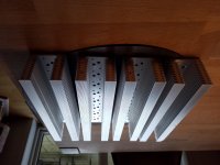
I have theese four sinks which measure 300mm long .70mm wide. 63mm high. They weigh 1.3 kilogram each, is one for each channel enough? I read that the low tim requires 0.67 degrees c/w and the super half of it, I have no data on theese sinks, I would like to mount them horizontally on chassis, which decreases proper airflow, as I have four sinks I could use two or channel but that would risk thermal runaway.
All thoughts are welcome
Btw I'm not interested in fan assist.
I currently building the leach superamp, and have a question regarding heatsinks,
I have theese four sinks which measure 300mm long .70mm wide. 63mm high. They weigh 1.3 kilogram each, is one for each channel enough? I read that the low tim requires 0.67 degrees c/w and the super half of it, I have no data on theese sinks, I would like to mount them horizontally on chassis, which decreases proper airflow, as I have four sinks I could use two or channel but that would risk thermal runaway.
All thoughts are welcome
Btw I'm not interested in fan assist.
Attachments
Your dimensions are 300mm x .7mm x .63mm?
Even if they're 300mm x 70mm x 63mm, the Leach Amp boards would be bigger. You want heatsinks that will be at least the same length and width if not bigger.
Even if they're 300mm x 70mm x 63mm, the Leach Amp boards would be bigger. You want heatsinks that will be at least the same length and width if not bigger.
Yes they are 300mm x 70mm x 63mm and accommodate 8 to-3 transistors each which is just perfect, I'm not sure I get your point, the board will connect to the output transistors via cables, so the shape can't matter much or ?
Maybe test by mounting a transistor on one, lay it horizontally, and pump about 10W thru the transistor and measure the thermal rise. They are big sinks, but not that much surface area. I'd run the test for a good bit of time to let the thermals settle.
I thought they might be inadequate, could they be cut in half and mounted side by side on aluminium plate, vertical, ? This might require some actual power testing, I want it done right the first time
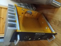
I found a old amp chassis that will fit nicely, I will cut the four sinks in half and mount them as shown, with two outputs pr sink, my concern is the four biasing diodes, to avoid thermal runaway, obviously the four sinks must be mounted good on a aluminium plate with thermal grease between, could I split up the four diodes one to each sink or should they be close together as mr leach teached, once again I would like it to work the first time ,hence my questions, as to heatsinks ability to remove heat I'm confident it's more than enough this way. So how to mount those diodes?
Attachments
Yes, split the diodes up and thermally compensate the NPN and PNP banks separately. I’ve had to do this with big amps and it works perfectly. The good news about the superamp is that you only need to compensate the lower banks, so it only needs to be split in two, and if the upper and lower are not at the same temp you don’t have to worry about them tracking each other for current sharing. Voltage sharing is forced. You wouldn’t want to split the banks in half like that if they were all in parallel. I’ve tried. It fails. When I built my first “split up” 200 wpc amp I only compensated one bank out of the four and it ran away. Finally had to find bigger heat sinks so all devices in parallel could be on one sink. I built a pair of super leach-ish amps with +/-127 volt rails split into 4 banks, and separately compensated an NPN output, a PNP output, and both drivers. All parallel transistors were on common sinks. Never had the bias drift up, even with the plugs on the extension cords getting melty and the speakers starting to smell.
That’s more than enough heat sink, if you have 8 pieces mounted on the sides of that chassis. Maybe not enough for a continuous sine wave for hours, but your transformer might not take that anyway unless you’re using at least a 1500VA. For music, even running a PA, it’s plenty. 250 watts per channel really isn’t all that “big” anymore.
That’s more than enough heat sink, if you have 8 pieces mounted on the sides of that chassis. Maybe not enough for a continuous sine wave for hours, but your transformer might not take that anyway unless you’re using at least a 1500VA. For music, even running a PA, it’s plenty. 250 watts per channel really isn’t all that “big” anymore.
Thank you, that clarified my issues, I will split the diodes, I had a thought, for more accurate and fast tracking could the diodes be glued on top of the to3 devices ? Or is that just plain stupid and unnecessary?.
254 volts rail to rail, that's one big amp you build, not for newbie to poke around in.
254 volts rail to rail, that's one big amp you build, not for newbie to poke around in.
In that big amp I clamped the “diodes” directly to the top of the TO3’s. The “diodes” were diode-connected BD139’s. That really only works with metal cased transistors - it is tempting to clamp them to flatpacks as well, but with those thermal tracking is better if you mount to the heat sink. The epoxy case doesn’t heat up as fast as the heat sink next to the mounting surface.
TO-126 (or even 220j are way easier to work with than DO-41 or 35. I once bought a batch of surplus BDX77’s (TIP41-ish in an iso-220) and used them all up for thermal tracking diodes and vbe multipliers.
TO-126 (or even 220j are way easier to work with than DO-41 or 35. I once bought a batch of surplus BDX77’s (TIP41-ish in an iso-220) and used them all up for thermal tracking diodes and vbe multipliers.
Reminds me of my heating system , water tubes in the concrete floor, adjust the thermostat and I'll notice the difference in minimum two hours.
I to have a stash of bd139, when the sinks are finished and assembled I will experiment a bit.
Thanks for your invaluable inputs.
I to have a stash of bd139, when the sinks are finished and assembled I will experiment a bit.
Thanks for your invaluable inputs.
By the way, I have been looking extensively for a review of a leach amp, it doesn't have to be the superamp, just a low tim by Dr leach hand, I can't find any, do you guys know any sources?.
As has been pointed out, the diode body transfers heat to the PN junction relatively slowly. I clamped the diode LEADS, via a Kapton insulator, to the heatsink, a much faster heat transfer mechanism.
Brian
The real problem with round diodes is making contact to the body. It only happens at one point. And of you put pressure on it you’ll crush it. And doing hokey things to make heat transfer “happen” invites shorting things out. You want to be able to drop an amp a foot or so, pick it up, and plug it in without wondering if it’s going to explode.
Some years ago, I built a Leach amp with the ON Semi ThermalTrak devices, where you have the 3281/1302 power transistors with a built in diode. That was very handy for construction and the bias was very stable.
Remember, Dr. Leach died over 10 years ago.
The Google machine pointed me to this and others:
As you've probably seen from his profile at Georgia Tech's website, Professor W. Marshall Leach, Jr., is a highly distinguished academician in the field of electrical engineering. Around 1980 he had his own company, "LSR&D, Inc." which manufactured The Leach Superamp monoblock amplifiers ($1598 per pair, at that time), and also a lesser stereo model.
They were reviewed by Peter Aczel in "The Audio Critic" vol. 2 no. 3, Spring through Fall, 1980. That was well before Mr. Aczel went over to the dark side and adopted the belief that all amplifiers meeting certain basic criteria sound the same. He named the Superamp "the best-sounding high-powered amplifier tested so far, regardless of price."
If you wish, contact me through Audiogon and I'll email to you a scan of the review.
Regards,
-- Al
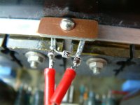
A little update, this is the core amplifier, tubular metal chassis to support the 16 kilo power supply, 65 volt quad secondary, 2kw, 200000uf in total capacity.
I'm waiting for aluminium sheet, top, sides buttom, front, all 3mm except front which is 8mm, with leach triple transistor logo engraved.
I'm waiting for aluminium sheet, top, sides buttom, front, all 3mm except front which is 8mm, with leach triple transistor logo engraved.
- Home
- Amplifiers
- Solid State
- Leach superamp heatsink question