Threshold, SAE, Bozak, used three outputs in series back in the day....
Glad those days are gone.
Glad those days are gone.
So that I can understand, are you guys saying that stacking the transistors in series is lossy? Is it more efficient to to run higher voltage transistors and not stack them? If so, what would be the reason for building a Leach Superamp? Wouldn't you be better off just building the Low TIM with higher rated transistors? Seems to me that the difference is the stacked in series outputs.
Can someone explain this a little better?
Thanks, Terry
Can someone explain this a little better?
Thanks, Terry
Re: Transistors
With regards to the topology, there were never any official boards that Dr. Leach offered for the super amp. He only had a couple of prototype units built for himself by graduate students. I received a pair of boards a while back that someone on this forum had made (forget who it was), and I managed to build a 1 channel superamp, but never ended up using it for anything. As far as I know now, there are no boards out there available for the superamp.
There is definately room to evolve the design into something different, but it might be best to first decide what the goals of the project are.
--
Brian
JensRasmussen said:Well maybe you could not get any 250V devises at the time the amp was constructed.
Therefore there was a need to stack the output
Maybe if people want to build the exact same thing that Dr. Leach designed, they should get the original boards?
\Jens
With regards to the topology, there were never any official boards that Dr. Leach offered for the super amp. He only had a couple of prototype units built for himself by graduate students. I received a pair of boards a while back that someone on this forum had made (forget who it was), and I managed to build a 1 channel superamp, but never ended up using it for anything. As far as I know now, there are no boards out there available for the superamp.
There is definately room to evolve the design into something different, but it might be best to first decide what the goals of the project are.
--
Brian
Just a reminder:
BJT transistor can not exceed SOA at any moment or they will die.
Exceed max dissipation at a given temperature for only few milliseconds and they are dead.
The number of transistors used depends on dissipation at a specific load.
Often only a few parallel output devices are capable of tremendous currents, but even at a much smaller current going through the outputs dissipation may be too high and away they go.
With a larger number of outputs the output stage may drive lower impedance loads.
For the number of output devices the question for the lowest impedance level needs to be answered first.
btw :
If you have read the Leach papers correctly you will know that Marshall Leach designed his amplifier at the time that Mati Otala had published his TIM work. Professor Otala's work was certainly not accepted as the utter truth right away.
Leach made his amplifier in the 70s and published it for diy purposes to show the benifits of low transient intermodulation.
The original Leach amp i built long ago, and is no attraction anymore.
Professor Leach revised his amplifier many times, the current one is the product of an evolution.
The original was intended for diy people, the last one was.
SO; no exotic parts, just regular easy to obtain power transistors.
In time, Marshall Leach may very well do a revision on his amplifier, who knows.
Fact is that he intended his design as a step forward, a revolution in amp designing, the same way Pass does.
Saying that it is best to keep it as it is, use the parts that were used instead of improved ones, means not understanding how the amp was born and how it evolved, especially this amplifier.
I have spoken to a couple of amplifier designers in the 80s, the usual answer for not going for more exotic parts at the time was that easy, regular, secure parts supply was an important factor.
Notice the amp companies in NZ and Oz using the most modern latest parts, being close to the origin must have contributed.
Once again I implore folks to actually read the documentation!
Then take some effort to intellectually understand it.
The most recent page revision is 07/17/03.
Once again from
http://users.ece.gatech.edu/~mleach/superamp/
"I do not have circuit boards for the Double Barrelled Amplifier. If you wish to build it, you must make your own. Two drawings show the parts layout on the board, one with circuit traces and one without. These are scaled by a factor of 1.5. The other shows the circuit traces only. All layout views are from the component side of the board. You must flip the layout for the foil traces over to obtain the solder side view. The circuit board measures 4 inches by 6 inches. To my knowledge, there are no errors in the layout. If you decide to use it, you should carefully check it for errors because I could have easily made a mistake."
BTW, the plastic transistors you folks are so in love with do not go on the driver board. They are mounted on the heatsink. A careful examination of the circuit will demonstrate the difficulty of getting the plastic power transistors on the board and attached to the heatsink at the same time without wires.
Been there, done that, got the T-shirt.
Prosit
Re: Re: Transistors
Hi Brian,
Nice to see you 🙂
I was thinking about the design on the super amp page.....
\Jens
Hi Brian,
Nice to see you 🙂
BrianGT said:
With regards to the topology, there were never any official boards that Dr. Leach offered for the super amp.
--
Brian
I was thinking about the design on the super amp page.....
\Jens
BTW, the plastic transistors you folks are so in love with do not go on the driver board. They are mounted on the heatsink. A careful examination of the circuit will demonstrate the difficulty of getting the plastic power transistors on the board and attached to the heatsink at the same time without wires.
Been there, done that, got the T-shirt.
Prosit
I think it's easy to mount plastic transistors on a heatsink. Even if they connect to a PCB...... I too have a T-shirt 😉 from when I made my own PCB layout......

\Jens
Hallo JensRasmussen,
And a beautiful piece of work it is.
We now have exactly 2 folks who have built THIS beast.
"SO; no exotic parts, just regular easy to obtain power transistors.",
My goodness, what a concept for the DIY'er.
The real challenge might be "to keep it as it is, use the parts that were used instead of improved ones" while allowing anyone to use the "improved" ones at their own peril. Now that would be a real accomplishment.
Let's see, we'll use high power plastic transistors. Ummm, how big must the heatsink be?
Don't want to discourage. Just practical questions folks.
Prosit
acenovelty,
The TO-3 case transistor is becoming aged now and TO-247 and TO-3P are far more common. That is why they are trying to incorporate them into the design. I just don't understand your resistance to improving the design. Another advantage of using the newer transistor packages is that the boards can be designed to minimize the use of hardwiring. I think that is a good thing. Jens is going to redesign the board to make it a bit more updated with respect to the output transistor packaging and making it a bit easier to build, thats all. Why are you so opposed to that? It just doesn't make sense. Are you against making the parts easier to get, possibly cheaper and making it easier to build?
The TO-3 case transistor is becoming aged now and TO-247 and TO-3P are far more common. That is why they are trying to incorporate them into the design. I just don't understand your resistance to improving the design. Another advantage of using the newer transistor packages is that the boards can be designed to minimize the use of hardwiring. I think that is a good thing. Jens is going to redesign the board to make it a bit more updated with respect to the output transistor packaging and making it a bit easier to build, thats all. Why are you so opposed to that? It just doesn't make sense. Are you against making the parts easier to get, possibly cheaper and making it easier to build?
BrianGT, I am going to correct you on the statement that there were no official boards from Dr. Leach.
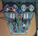
I bought four of them from him in 1984 and back then it was called the double barrel amp.
My super amp featured gain matched transistors for each stage, a fully regulated power supply for gain and current stages, 4 -500VA Toroids, inrush protection, dual mono format, bypassed caps and separate power feeds for the gain versus current stages. ( This trick is seldom done, but it minimizes the voltage modulation effects due to the high current to the output stages) . No current limiters were used as we depended on the regulator for protection.
It was very difficult getting surplus 110 or 120V Computer Grade electrolytics that a grad student could afford. We finally scored some in Seattle. For the regulators we used a design by Boak that Walt Jung had refined. It featured pre-regulators and foldback protection.
The amp was over 100lbs when it was finished.
How did it sound? Effortless as you would expect. It made my B&W 802s come alive. Unofrtunately KRELL's beast, ( Can't remember the model) was a tad better.
The weak point in the amp was the long wiring to all the TO3s. So redesign without the wires would be really good.
Wow 20yrs ago!!!
Hello kilowattski,
Aged? Seems we can find many metal case transistors that are high power, etc. that will suit the purpose.
(c)RAP music is more common now. Does that make it better?
"improving" the design? Have there been any suggestions other than the use of plastic transistors that would "improve" the design?
"minimize the use of hardwiring"? Hmmm, How many legs on a plastic resistor? Answer. 3 How many legs on a TO3? Answer. 2 plus a common connection to the case.
I have posed some practical questions no one seems willing to address. Choose to use the MJL21194, how many devices? What will the resultant power be at what voltage? What other changes need to be made to the driver board? How big must the heatsink be to dissipate the heat?
" parts easier to get, possibly cheaper "
MJ15003 from onsemi.com $1.87 TO3
MJL1302 from onsemi.com $2.88 TO264
MJW21193 from onsemi.com $2.45 TO247
MJL21194 from onsemi.com $2.88 TO264
All perfectly suitable. More choices available.
Easier to build? What could be changed "on the board" that will make it easier to build? Answer. One could make copper trace connections to the output devices soldered directly on the board.
In principal it seems that has been done.
http://home.swipnet.se/malman/LeachAmp.html
What other "improvements" can you or others offer?
Prosit
Attachments
Mikett said:BrianGT, I am going to correct you on the statement that there were no official boards from Dr. Leach.
I bought four of them from him in 1984 and back then it was called the double barrel amp.
My super amp featured gain matched transistors for each stage, a fully regulated power supply for gain and current stages, 4 -500VA Toroids, inrush protection, dual mono format, bypassed caps and separate power feeds for the gain versus current stages. ( This trick is seldom done, but it minimizes the voltage modulation effects due to the high current to the output stages) . No current limiters were used as we depended on the regulator for protection.
It was very difficult getting surplus 110 or 120V Computer Grade electrolytics that a grad student could afford. We finally scored some in Seattle. For the regulators we used a design by Boak that Walt Jung had refined. It featured pre-regulators and foldback protection.
The amp was over 100lbs when it was finished.
How did it sound? Effortless as you would expect. It made my B&W 802s come alive. Unofrtunately KRELL's beast, ( Can't remember the model) was a tad better.
The weak point in the amp was the long wiring to all the TO3s. So redesign without the wires would be really good.
Wow 20yrs ago!!!
Sorry for the mistake, I meant to say that there are currently no official boards offered by Dr. Leach. He only sells the ver 4.5 Leach amp boards.
--
brian
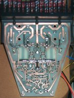
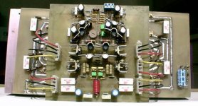
acenovelty said:Bottom side of Klas Malman's board.
Granted this is the Low TIM amp, but does not the same principle apply?
I see no reason to still use the old TO-3 devices, when the newer devices are cheaper, easier to obtain, and allow for more flexible chassis design.
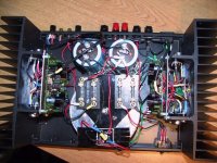
As for the board, if it is made with output boards, then the option could be there for using both types of devices with expansion boards, or wiring the devices with wires, as done with the original amp (the most tedious part IMO).
Here is a pic of an amp that I helped a friend build using the newer devices:
--
Brian
Attachments

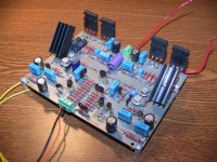
BrianGT said:Compared to my working prototype amp using the new devices:
--
Brian
Brian, did I miss something, will you be offering some form of leach PCB's?
BTW did you look for the Control PCB for me, stuffed or blank?
Regards
Anthony
Coulomb said:
Brian, did I miss something, will you be offering some form of leach PCB's?
BTW did you look for the Control PCB for me, stuffed or blank?
Regards
Anthony
I made that Leach amp board 2 years ago just to see if I could do it, and I never got around to getting more than just a couple of prototypes made. I was going to shrink down the layout and get a production run made, but I got tied up in school work.
I have 3 control boards for the cdpro2 in my pcb collection currently, drop me an e-mail and we can talk about it. I definately need to keep 2 of them for prototyping my new cd player project, but I can spare 1.
--
Brian
BrianGT,
"the newer devices are cheaper"?
MJ15003 from onsemi.com $1.87 TO3
MJL1302 from onsemi.com $2.88 TO264
MJW21193 from onsemi.com $2.45 TO247
MJL21194 from onsemi.com $2.88 TO264
Perhaps you would like to explain how this is true?
"As for the board, if it is made with output boards, then the option could be there for using both types of devices with expansion boards, or wiring the devices with wires"
Now that is a really good idea.
Attachments
acenovelty said:BrianGT,
"the newer devices are cheaper"?
MJ15003 from onsemi.com $1.87 TO3
MJL1302 from onsemi.com $2.88 TO264
MJW21193 from onsemi.com $2.45 TO247
MJL21194 from onsemi.com $2.88 TO264
Perhaps you would like to explain how this is true?
"As for the board, if it is made with output boards, then the option could be there for using both types of devices with expansion boards, or wiring the devices with wires"
Now that is a really good idea.
I guess I was wrong again on the pricing... Digikey carries all of the devices for easy ordering from the states. I believe that Onsemi also ships their samples through Digikey now, like TI does.
--
Brian
- Status
- Not open for further replies.
- Home
- Amplifiers
- Solid State
- Leach Super Amp Pcb Re-Design (LSAPRD)