Hi,
Im currently trying to get a working sim of the Leach low TIM amplifier V4.5
I have made the circuit simple by removing the protection as Dr Leach has mentioned is possible on his website.
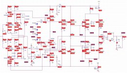
The circuit works but the bias is extremely high, ill attach a picture of my PSPICE simulation with bias currents and some voltages marked.
The reccommended value for the bias POT (RBIAS in my circuit) is 2K and with it set at 2K i am still unable to get a sensible bias of 100mA per rail, im seeing 700mA per rail!
If anyone can help / see my error it would be much appreciated.
Regards
Craig
Im currently trying to get a working sim of the Leach low TIM amplifier V4.5
I have made the circuit simple by removing the protection as Dr Leach has mentioned is possible on his website.
The circuit works but the bias is extremely high, ill attach a picture of my PSPICE simulation with bias currents and some voltages marked.
The reccommended value for the bias POT (RBIAS in my circuit) is 2K and with it set at 2K i am still unable to get a sensible bias of 100mA per rail, im seeing 700mA per rail!
If anyone can help / see my error it would be much appreciated.
Regards
Craig
Attachments
Last edited:
your sim shows >3.4V biasing the pre-driver stage.
That is the cause of the excessive output bias.
Investigate what the Vbe multiplier is capable of doing. Then adopt the 4diode version that Leach uses and investigate what it does that is different.
Then when you know the operation you will know what to tell the simulator to get a sensible bias voltage and output bias current.
😕 Triple darlington gives 6 forward biased junctions which would mean 3.4 volts is probably under biased. (6 time .6 is 3.6). I suspect something is screwy in simulation software. Half volt Offset is not reasonable - large discrepancies between the collector and emitter currents in the outputs,less than a volt drop across the first two driver transistor b-e junctions, and very unbalanced input transistor currents for starters. (BTW hard to read some of the numbers). Numbers just don't seem right?
Beware of where you get your spice models from. A few of Onsemi's are just plain wrong, causing problems like this. I seem to recall problems with the MJE340/350 models, so I use the ones from Fairchild.
Hi
Thanks for the replies, I appreciate the help.
Andrew, After reading your post i stumbled on an old thread debating the VBE multiplier and its shortcomings in this amp. It will make for an interesting read I think. Ill find out about this slightly special multiplier.
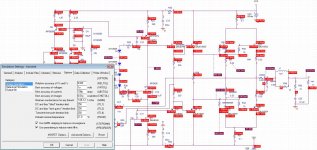
sregor and Jaycee, I think you are both right, I adjusted the .OPTIONS properties to be as in the attached photo and I am getting much more sensible voltages around the circuit. The bias is now only an order of magnitude too high which is better than before.
Im now beginning to suspect the MJE models Jaycee mentioned.
Does this image look more down to earth?
(i had to increase ABSTOL to get convergence, im new to SPICE and ive learned fiddling about can make a lot of difference with .OPTIONS!)
Cheers
Craig
Thanks for the replies, I appreciate the help.
Andrew, After reading your post i stumbled on an old thread debating the VBE multiplier and its shortcomings in this amp. It will make for an interesting read I think. Ill find out about this slightly special multiplier.
sregor and Jaycee, I think you are both right, I adjusted the .OPTIONS properties to be as in the attached photo and I am getting much more sensible voltages around the circuit. The bias is now only an order of magnitude too high which is better than before.
Im now beginning to suspect the MJE models Jaycee mentioned.
Does this image look more down to earth?
(i had to increase ABSTOL to get convergence, im new to SPICE and ive learned fiddling about can make a lot of difference with .OPTIONS!)
Cheers
Craig
Attachments
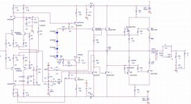
Can't see what's going on at the input side. The biggest thing that sticks out still is the VBE drops and the hfe for the outputs and driver, especially the outputs. Vbe drop is only 475 mV for the qmj15003 output, but hfe is over 400 (1.03 mA base producing 485 mA emitter current, also similar for qmj15004. The qmje15030 and 15031 also have current gains of over 150 - don't have the spec sheet but seems high. Keep going.
replace all of the MJ models with another make of device.
Check the DC conditions at the input.
I see 15uA & 1.5uA on the -IN LTP and 12uA & 84nA on the +IN side.
Check the DC conditions at the input.
I see 15uA & 1.5uA on the -IN LTP and 12uA & 84nA on the +IN side.
Excellent, I think the issue is solved now, entirely due to poor SPICE models from ON semi.. thanks ON Semi.. 😀
For anyone who is having similar problems, this cocktail of spice models seems to give the correct operating point:
Outputs are Andy_C's:
Improved SPICE Models for MJL3281A and MJL1302A - Section 1
Drivers are: (ON MJE1503x do not work properly at DC!)
http://www.diyaudio.com/forums/parts/6348-spice-models-2sa1837-2sc4793.html
and predrivers are:
Fairchild Semiconductor - Discrete PSPICE: Bipolar Transistor Models
The diff pair are MPS8099/8599
.model MPS8599 PNP(Is=10.68f Xti=3 Eg=1.11 Vaf=100 Bf=187.7 Ne=1.401
+ Ise=26.07f Ikf=.2203 Xtb=1.5 Br=1.833 Nc=2 Isc=0 Ikr=0 Rc=.8
+ Cjc=14.16p Mjc=.5585 Vjc=.75 Fc=.5 Cje=25.11p Mje=.3626 Vje=.75
+ Tr=358.6n Tf=591.1p Itf=1.5 Vtf=12 Xtf=50 Rb=10)
* Motorola pid=MPS8598 case=TO92
* 88-09-13 bam creation
.model MPS8099 NPN(Is=4.872f Xti=3 Eg=1.11 Vaf=100 Bf=9.599K Ne=1.315
+ Ise=14.65f Ikf=.1434 Xtb=1.5 Br=6.935 Nc=2 Isc=0 Ikr=0 Rc=.7
+ Cjc=5.805p Mjc=.4312 Vjc=.75 Fc=.5 Cje=10.49p Mje=.4602 Vje=.75
+ Tr=565p Tf=407p Itf=.18 Vtf=3 Xtf=2.5 Rb=10)
* National pid=18 case=TO92
* 88-09-07 bam creation
Many thanks!
The MJE1503x models are wrong too ? ffs :x
Fairchild have everything you could want for a power amp TBH:
KSA992/KSC1845 for small signal
KSA1381/KSC3503 for VAS and predrivers
KSA1220/KSC2690 for low power drivers
FJP1943/FJP5200 for higher power drives
and then their own clone of the Toshiba 2SA1943/2SC5200 in both TO3P and TO264 package
and most importantly, good reliable SPICE models for all of them!
Yep they certainly didnt behave..
Fairchild are easily champing over ON semi in my 'What SPICE model' book!
Fairchild are easily champing over ON semi in my 'What SPICE model' book!
- Status
- Not open for further replies.
- Home
- Amplifiers
- Solid State
- Leach Low TIM 4.5 bias problem