can you post actual pictures? time to test at full voltage using the 10ohm current limiting resistors...if you have a variac, that would even be better...
I can post a photo tomorrow. I have variac, and will hook up with 100ohm resistors tomorrow as well.
Can you verify the placement and value of Q2?
The input voltage of .324V is not right (if that is measured on the base of Q2). Either you have the wrong transistor or it is mounted incorrectly.
The input voltage of .324V is not right (if that is measured on the base of Q2). Either you have the wrong transistor or it is mounted incorrectly.
From your DC readings it appears that from the VAS onwards all transistors are in cutoff state. The output node and many other nodes are in high impedance floating state and the DC feedback loop is not properly closed, the DC readings at these nodes therefore are not very reliable due to the high impedance state.
The voltage drop across R9 indicates about a 1mA emitter current of Q3, yet we see almost no current over R12, and almost zero Vbe at Q6. Q6 may have a short out b-e junction.
The voltage drop across R9 indicates about a 1mA emitter current of Q3, yet we see almost no current over R12, and almost zero Vbe at Q6. Q6 may have a short out b-e junction.
From your DC readings it appears that from the VAS onwards all transistors are in cutoff state. The output node and many other nodes are in high impedance floating state and the DC feedback loop is not properly closed, the DC readings at these nodes therefore are not very reliable due to the high impedance state.
The voltage drop across R9 indicates about a 1mA emitter current of Q3, yet we see almost no current over R12, and almost zero Vbe at Q6. Q6 may have a short out b-e junction.
Okay, that seems like a good hypothesis. I'm going to simulate that failure mode on Q6 and see if it makes sense with my measurements. I'll get back to you shortly. Thanks! It's just helpful to get another set of eyes on the data, since I've been staring at it so long.
-Evan aka bperboy
Okay, I have simulated the circuit with a failure on the E-B junction of Q6, and it appears consistent with my measured results. I will replace Q6 tomorrow morning and see what happens!
using the voltages you have or get in the future, calculate and mark on the currents flowing through resistors.
You should see current errors and thus point you to semiconductor errors.
Turn you bias voltage down a lot and power up via a bulb tester.
The Zeners on the input side are sitting at 17Vdc so the front end is seeing near half working voltage. Do you have two 20V in series for 40Vdc on each side? That will affect operation.
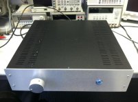
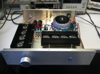
Okay, Q6 was the problem. I replaced it this morning, and I get great results now! Power out per channel is around 80-85Wrms, this due to +-50V rails instead of 58V rails. This was done because I already had a transformer that was almost suitable (35VAC secondaries instead of 40VAC).
I have attached some photos!
I have taken frequency response data at 50Wrms output power.
Measure 20mV DC offset on one channel, 1.01mV offset on the other. Biased to about 90mA with no load, no input.
Let me know if you have any questions about the amp!
I have attached some photos!
I have taken frequency response data at 50Wrms output power.
Measure 20mV DC offset on one channel, 1.01mV offset on the other. Biased to about 90mA with no load, no input.
Let me know if you have any questions about the amp!
Attachments
good job....the leach amp is a tried and tested, validated design, built by thousands around the globe.....no reason not to make it work.....😀
Fit over temperature switches to both heatsinks. These heatsinks have the potential to overheat and destroy your amplifier, if you are careless.
Twist your cable pairs, everywhere.
Twist your cable pairs, everywhere.
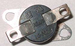
thermal cut off showm in post 31 if you use 12 volt dc protector wire the 12 volt positive in series with cut off when amp cuts off at high temprature load is also dissconnected as dc protect relay will cut off
"relay will cut off "
That's a good idea. Many use the cut-off devices on the transformer or in series with the load. They don't like to interrupt a lot of current, so in the coil of a relay makes a lot of sense.
That's a good idea. Many use the cut-off devices on the transformer or in series with the load. They don't like to interrupt a lot of current, so in the coil of a relay makes a lot of sense.
Hello everybody!
I built a Leach Amp quite a while ago and reactivated it this week. When I power it up, it does quite a "plopp" in the speakers which doesn`t disturb me.
What I don`t understand is the fact, that while it plopps, the membrane of the left channels speaker moves outwards, while the membrane of the right speaker moves inwards...
Does anyone here has an idea what might be the reason for this behaviour?
Sound of the amp is quite good. The Amp is completely dual mono, with 2 PSU (also 2 transformers).
I checked all the connections and polarity, but did not find anything. One idea I have is the polarity of the rectifiers, but i don`t know if that might be the reason.
I would be glad if someone could help!
The offset could be due to a difference between which rail powers up and stabilises the fastest, or it could just be down to an imbalance in the input pairs, that goes one way in one amp and one way in the other, that could be magnified upon powering up.
A Leach Amp should not do "quite" a plopp at power on/off unless the transistors are way out of matching. However, when it does happen, the plopp could be either way as the DC transient at the amp output can be positive or negative, depending on the way the transistors were mismatched.
Just build a speaker relay if the power-on transient bothers you. Mooly has a simple and good design using traic.
Just build a speaker relay if the power-on transient bothers you. Mooly has a simple and good design using traic.
5th Element and nattawa,
thanks you for your replies. My concern was if the different "directions" of the "plopp" on powering up would mean that the phase is reversed during normal operation of the amp. (Speaker membranes working in opposite directions all the time when playing music and not only on powering up).
As I understand your replies, the behaviour on start up does not mean one amp is working in inverted phase, is that right? (As you might have guessed by now I`m new to building amps, so help is very appreciated)
- Status
- Not open for further replies.
- Home
- Amplifiers
- Solid State
- Leach amp troubleshooting