Hi Shadow,
Sorry to be the bearer of bad news,
To use a 2x21V transformer, you would need to use 2 such transformers to get the correct voltage you can connect the 2 windings of each transformer in series as per the 2nd picture above then connect the end of the 1st transformer to the beginning of the 2nd transformer and use that junction as the CT
You will need about +/-60 and a single 2x21V transformer cannot do this.
If you need any good transformer company in Slovenia, tell me and I will send you some telephone numbers.
Supernet!
Supernet!
Supernet i'm looking for cheap ones.And probaly the cheapest is HIT Elektronik.6k SIT for 500VA toroid.
Tested 2x21V
Now i tested amp with 2x21V secondary and works OK.Power supply puts unloaded voltage 62V,loaded 60V.
If you all thinks 2x21 is low how then amp even works?
If someone have some measurment method to test supply be very velcome to tell me,specialy AudioFreak.
Anyway i dont know what test i have in mind,multimeter probaly dont lie 🙂
Hi again,
shadow:
I'm a little curious about your amp. It is amazing that it actually works at all, though Prof. Leach states that one can measure amplification from 8 Volts and up. I think your amp works fine, but you'll never get your 120 Watts per channel using that trafo.
What you have is probably 60 volts, when you measure from V+ to V-. When I measure mine, I have 115 volts between V+ and V-. You should have just above 55 volts between V+ and Ground (and -55 volts between V- and ground).
If you use your multimeter and measure between the collector on Q14 and Ground, what is the reading? (If you have used the recommended 2n3439 or the 2n3440 the collector is connected to the metal casing on the transistor, which makes it really easy to measure there).
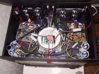
On the attached picture, you can see my trafo. It is a 2x38 volt Toroid transformer. The green and the blue cable is connected to the rectifiers. The red and brown cable is connected to ground(eg, the rats nest on the leftmost capacitor bank). All references to ground are connected there, including the ground pin on the powercord.
Good luck!
//magnus
//magnus
shadow:
I'm a little curious about your amp. It is amazing that it actually works at all, though Prof. Leach states that one can measure amplification from 8 Volts and up. I think your amp works fine, but you'll never get your 120 Watts per channel using that trafo.
What you have is probably 60 volts, when you measure from V+ to V-. When I measure mine, I have 115 volts between V+ and V-. You should have just above 55 volts between V+ and Ground (and -55 volts between V- and ground).
If you use your multimeter and measure between the collector on Q14 and Ground, what is the reading? (If you have used the recommended 2n3439 or the 2n3440 the collector is connected to the metal casing on the transistor, which makes it really easy to measure there).
On the attached picture, you can see my trafo. It is a 2x38 volt Toroid transformer. The green and the blue cable is connected to the rectifiers. The red and brown cable is connected to ground(eg, the rats nest on the leftmost capacitor bank). All references to ground are connected there, including the ground pin on the powercord.
Good luck!
//magnus
//magnus
Attachments
You are right.
Yes i measured 28.8V DC between the collector on Q14 and Ground and that is too low.To put in other words you are right 🙂
So if i use 2x42V secondary transformer wich is probaly good choice,from where i can take + and - for both channels?
I use only one bridge rectifier.
I allready solved this:for one channel + i take from filter caps and - from central ground point.For second channel i take - from filter caps and + from central ground point.
From this is clear that one +(one channel) and one -(second channel) is shared right on central ground point.
Amp will work with that kind of wiring?
With prof. Leach suggestions for a transformer with 80V secondary and his power supply circuit (voltage taken from + and - filter caps),how can his power supply puts out 40V DC?
And not 113V DC.
And not 113V DC.
according to the literature on prof. leach's website, the rails are +/- 58V the ~120Vdc is between +ve and -ve supply rails not between +ve and ground or -ve and ground. CT transformers like the one prof. leach are rated according the the difference in voltage between the start of the winding and the end of the winding. so a 80V CT is equivalent to 2 x 40V secondaries both of which will give rails of just under +/-60Vdc.
Hi!
shadow: What you need to get is a 2x38 volt (or 2x42 volt) transformer. That way, you'll at least have a chance on getting it right.
On my transformer I connected my wires like this: (note that the colors on your transformer might be different)
This should do.
//magnus
shadow: What you need to get is a 2x38 volt (or 2x42 volt) transformer. That way, you'll at least have a chance on getting it right.
On my transformer I connected my wires like this: (note that the colors on your transformer might be different)
Code:
        Green       Red/Brown    Blue
          I             I         I
          AC           GND        AC
           \                        /
            \                      /
             \                    /
              \                  /
               \                /
                \              /
                 \            /
                  \          /
                   I        I
    pos------------- Rectifier ---------neg
     I                                   I
     I                                   I
     I                GND                I
     I                 I                 I
    pos  CAP 1 neg-----+-----pos  CAP 2 neg
     I                                   I
     V+                                  V-
This should do.
//magnus
I see what you trying to say i'm using this type right now,but my multimeter reads double voltage.Like 2x42Vsec. i'm reading 140V DC and not 60V AC.
I read 60V with this:
Green Red/Brown Blue
I I I
AC GND AC
\ /
\ /
\ /
\ /
\ /
\ /
\ /
\ /
I I
pos------------- Rectifier ---------neg
I I
I I
I GND I
I I I
pos CAP 1 neg-----+-----pos CAP 2 neg
I I I
V+(left ch.) V-(left ch.), V-(right ch.)
V+(right ch.)
Shoud i ignore high voltage reads,cause i dont know what kind of mistery is hidden here.
I measured 28.8V DC between the collector on Q14 and Ground with this transformer,and with wiring as your picture shown i measured 60V.😕
So if i measure with right transformer voltage(like your picture not my) 140V DC then this is only 60V DC but i might loose output transistors if real voltage is 140V DC 😕 😕
Shadow:
You probably mean this (which is not recommended for the Leach Amp):
In which case, I reallly recommend you to rewire your amp to look like mine. In your case, the V- has the same potential as ground (=0 volts).
Try and measure between the metal casing on Q15 and Ground on both your boards. On one of your boards your multimeter should read 0 volts if I understand your schematic right. On the other, it should be 0 volts between Q14 and ground. THIS IS NOT CORRECT!
I'm still amazed that your components has not yet started burning. ;=)
Try and connect like this instead:
AND!!!! Make sure that if you measure voltage across the outputs on the transformer you get the HIGHEST reading between Green and Blue! AND 1/2 the voltage between Green and Red, which should be equal to the reading between Red and Blue.
Regards,
//magnus
You probably mean this (which is not recommended for the Leach Amp):
Code:
I read 60V with this:
        Green       Red/Brown    Blue
          I             I         I
          AC           GND        AC
           \                      /
            \                    /
             \                  /
              \                /
               \              /
                \            /
                 \          /
                  \        /
                   I      I
  pos------------- Rectifier ---------neg
   I                                  I
   I                                  I
   I                GND               I
   I                 I                I
  pos  CAP 1 neg-----+-----pos  CAP 2 neg
   I                 I                I
   V+(left ch.)      I           V+(right ch.)
                     I
               V-(left ch.),
               V-(right ch.)
In which case, I reallly recommend you to rewire your amp to look like mine. In your case, the V- has the same potential as ground (=0 volts).
Try and measure between the metal casing on Q15 and Ground on both your boards. On one of your boards your multimeter should read 0 volts if I understand your schematic right. On the other, it should be 0 volts between Q14 and ground. THIS IS NOT CORRECT!
I'm still amazed that your components has not yet started burning. ;=)
Try and connect like this instead:
Code:
        Green       Red/Brown    Blue
          I             I         I
          AC           GND        AC
           \                      /
            \                    /
             \                  /
              \                /
               \              /
                \            /
                 \          /
                  \        /
                   I      I
  pos------------- Rectifier ---------neg
   I                                  I
   I                                  I
   I                                  I
   I                                  I
  pos  CAP 1 neg-----+-----pos  CAP 2 neg
   I                 I                I
   V+(left ch.)      I           V-(left ch.)
   V+(right ch.)     I           V-(right ch.)
                     I
                    GND
AND!!!! Make sure that if you measure voltage across the outputs on the transformer you get the HIGHEST reading between Green and Blue! AND 1/2 the voltage between Green and Red, which should be equal to the reading between Red and Blue.
Regards,
//magnus
No i have measured 30V between Q14,Q15 and ground on BOTH boards.And 0.2V between Q12,Q13 and ground on BOTH boards.
OK i'm waiting now for transformer so you can take a rest 😀
Then i try to solved this mess.
OK i'm waiting now for transformer so you can take a rest 😀
Then i try to solved this mess.
Sorry for interupt, but I got one question for Swede! Swede tell me what kind of soft start circuit do you use for toroid? Have you got any PCB layout for this circuit board?
Supernet
Supernet
Supernet sorry for another change of subject.
Where you from Supernet? I now Slovenia,but tell me wich town.
Thanks
Where you from Supernet? I now Slovenia,but tell me wich town.
Thanks
Murska Sobota i was hoped to be city near to me.OK i forgot before,tell me your E-Mail adress.
Thanks
Thanks
- Status
- Not open for further replies.
- Home
- Amplifiers
- Solid State
- Leach Amp strange things