whats the typical resistance of a speaker coil, I would expect it to be very low. If a theoretical speaker were a pure inductor would it not consume power?
for a nominally rated 8ohm speaker, typical dc resistance is about 6ohms...
Hi Carl this is a nice board, but Im wondering if it would be better with space for large diodes as the bridge you have doesnt look like it will cope with a 1000watt leach amp. Also CRC is a better approach and the Rs can allways be replaced with wire if the user doesnt want to use them.
Im not sure if I will be buying it depends on what the power supply ends up looking like, I have some big cans upto 75V, if I get into 100V territory I may be interested🙂
I agree. No way to heat sink those bridges, either. Also, more flexibility in bridge selection.
Also, it would have more flexibility in CRC arrangement if the plus and minus rails from each transformer were kept separate from the same of the other transformer instead of being tied together, and have an option to bridge them together at the ground output, or kept separate.
Luke, Tad & Pooge,
The bridge used in the shown power supply is a GBJ package device. You can fit a part from Diodes Inc (Mouser #621-GBJ2510-F) that is rated 1000V at 25A. That's a split bridge spreading the current over two devices making for a rectifier section that can sink 50A over the short term without breaking a sweat. The GBJ package is it's own heatsink and can deliver 5 amps nominal in free air (ie: 2 x 5A = 10A) without additional heatsinking. I think your concerns are covered.
The bridge used in the shown power supply is a GBJ package device. You can fit a part from Diodes Inc (Mouser #621-GBJ2510-F) that is rated 1000V at 25A. That's a split bridge spreading the current over two devices making for a rectifier section that can sink 50A over the short term without breaking a sweat. The GBJ package is it's own heatsink and can deliver 5 amps nominal in free air (ie: 2 x 5A = 10A) without additional heatsinking. I think your concerns are covered.
Luke, Tad & Pooge,
The bridge used in the shown power supply is a GBJ package device. You can fit a part from Diodes Inc (Mouser #621-GBJ2510-F) that is rated 1000V at 25A. That's a split bridge spreading the current over two devices making for a rectifier section that can sink 50A over the short term without breaking a sweat. The GBJ package is it's own heatsink and can deliver 5 amps nominal in free air (ie: 2 x 5A = 10A) without additional heatsinking. I think your concerns are covered.
Still, any advantage to your double-rectifier topology is wasted if you tie the transformer windings together.
Pooge,
The transformers windings are not tied together. The ground reference is taken after the bridge rectifiers.
The transformers windings are not tied together. The ground reference is taken after the bridge rectifiers.
Pooge,
The transformers windings are not tied together. The ground reference is taken after the bridge rectifiers.
Whoops. I should have said the caps are tied together at the ground point. All of the charging currents travel through this path. Also, all the charging currents from the amp board travel along the single line between the amp, and the ground on the PS board.
It would be better to tie these grounds together closer to the amp ground.
And a shot without the caps. Anyone interested in organizing a group buy? They would be $8 to $10 each dependent upon the number we buy.
I am in! 😀
Pooge,
I have no problem separating the grounds. That would be a simple change to the layout. I presume you are thinking of an 'off-board' star ground?
I have no problem separating the grounds. That would be a simple change to the layout. I presume you are thinking of an 'off-board' star ground?
Last edited:
Pooge,
I have no problem separating the grounds. That would be a simple change to the layout. I presume you are thinking of an 'off-board' star ground?
Yes. Exactly.
But if you modify the boards, why not include pads for bleeder resistors, maybe pads for possible RC damping across the output of each bridge, and especially add the abilility to add power resistors or inductors between the first and second caps, and maybe the second and third caps as well, to select the position of an R in the CRC for different sizes or quantities of caps used. These resistor positions could be bridged with a wire if resistors are not used.
I agree.
If one makes a PCB for a single project and it does it's job perfectly as is then one does not need any modifications.
If one offers a PCB that is completely inflexible in it's use then few will want it.
many more can if they wish come on board if they see it meeting their specific needs.
It often costs nothing to build in flexibility.
Pooge,
I invite you to scratch together a schematic of what you would like to see. Others please contribute as well. If you do that I will take a shot at wrapping a PCB around it.
I invite you to scratch together a schematic of what you would like to see. Others please contribute as well. If you do that I will take a shot at wrapping a PCB around it.
Pooge,
I invite you to scratch together a schematic of what you would like to see. Others please contribute as well. If you do that I will take a shot at wrapping a PCB around it.
I'll give it a shot, but I may not be able to do it this week. Getting ready to go out of town. I haven't done schematic drawings on computer lately. May be some time for a learning curve.
I think some of the features I suggested are self evident. I haven't studied your actual board, but keeping the +- traces very close together would be an advantage. Also, to make it more flexible for both power amps and preamps, or for separate front end and output supplies, you may want to consider being able to shorten the board to remove cap positions to save room. This would involve having output connections available at each cap location. You could create pads to jumper the "ground" side of each capacitor bank to a common ground as you now have, or leave the jumpers off.
Provide for board standoffs, if you haven't, that are isolated from ground.
Alternatively, or in addition, many bridges have heat spreaders. These types of bridges could be bolted to a chassis below the board, with vertical pins going up through the board. See the IXYS bridges at Partsconnexion, for example. While expensive, they are on sale right now.
Semiconductor HexFred Bridge Rectifiers
Democracy at work, great job Carl. I like being able to mount some crc resistors to the board also. Maybe a few holes for some aluminum housed items. The copper board itself will provide some degree of heatsinking on the ground plane.
Tad
Tad
Hi Pooge,
By using separate grounds, where do you intend to join them?
Are you thinking of joining the two wires directly on the GND in of the amp PCB?
By using separate grounds, where do you intend to join them?
Are you thinking of joining the two wires directly on the GND in of the amp PCB?
Andrew,
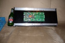
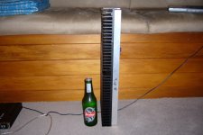
you wanted to know how much heatsink real estate I got, check this out.
Its my current UGS project. Most the metal work is done, Ive got a few more semis to place before I do the preliminary start up, check voltages etc before installing the chips, jfets and outputs.
The beer is Steinlager, an oldie but a goodie🙂
I bought four of these a few years ago for a good price and Ive not yet used them. As I dont have any monster class A's on my to do list for now, I thought I would use the other set for my Leach. Thats one reason i considered a Class A Leach.
Attachments
Pooge,
Those diode devices seem to be quite a find. A little bit on the pricey side though. Any chance of finding some middle ground on this. A set of 4 would be pushing 100.00. I like that 68 amp item. One of my smokiest areas on the build is the bridges. They go before anything else. It would be nice to incorporate a variac control on each amp. Bring the voltage up slow everytime you turn it on. More control than a softstart.
Have you ever been able to duplicate your Super Leach gerbers?
Tad
Hi Tad,
I found a page on the original leach clone that discusses the VI calculations. Be interesting to see how this compares with the spreadsheet. im tired now but might check it out closely tomorrow night.
I found a page on the original leach clone that discusses the VI calculations. Be interesting to see how this compares with the spreadsheet. im tired now but might check it out closely tomorrow night.
Pooge,
Those diode devices seem to be quite a find. A little bit on the pricey side though. Any chance of finding some middle ground on this. A set of 4 would be pushing 100.00. I like that 68 amp item. One of my smokiest areas on the build is the bridges. They go before anything else. It would be nice to incorporate a variac control on each amp. Bring the voltage up slow everytime you turn it on. More control than a softstart.
Have you ever been able to duplicate your Super Leach gerbers?
Tad
Did Jens ever make his Super Leach boards? Can any one comment on what the differences are apart from cascoding outputs? Is it just a high power Low Tim Leach?
Luke,
I think the entire amp is cascode. The differentials are the same, as the Low Tim, every other stage is multiple cascode. Some folks say this was done mainly because of the limited voltage 1970's era devices could handle.
Jens had the gerber files transferred to a couple of individuals for testing. He was not sure of wide spread use maybe infringing on Dr. Leach's intellectual property rights. Anyway the files are available but we need permission, from Jens, to use them
If you look under the Leach Super amp heading a complete thread discusses the development of the layout for the amp. The finished design is one quite large pcb.
I for one and many others would like to take on such a project. I cannot remember the members name who was doing the beta test on that project. He had the skills but not the time.
Using the Super Leach multiple cascode frontend with a multiple parallel output would probable work good with 350 volt plastic TO-247 devices. I would like some jfets in the frontend. Seems with the cascode and all that would be the choice of today.
I think with some more patients this may come to be.
Tad
Pooge,
Those diode devices seem to be quite a find. A little bit on the pricey side though. Any chance of finding some middle ground on this. A set of 4 would be pushing 100.00. I like that 68 amp item. One of my smokiest areas on the build is the bridges. They go before anything else. It would be nice to incorporate a variac control on each amp. Bring the voltage up slow everytime you turn it on. More control than a softstart.
Tad
Percy Audio has them cheaper, and quantity discounts.
The best way to go cheaper is to incorporate the ability to use individual diodes on the board. I still think heat sinking is a must for the amount of capacitance intended.
Heat sinking could just be mounting the diode or bridge heat spreader against the chassis. Thermal isolator pads would be required for individual diodes, probably not for the bridges. The individual components could add up to almost the bridge cost, plus the hassle of extra work.
There are many cheaper bridges or diodes that aren't soft recovery types. Those could be used to save money. In that case, an RC damper could be cheaply incorporated to reduce ringing. However, this would involve some work and measurement to figure out the values, as they would be, among other things, a function of the inductance of the transformer used. Depends how you want to use you time, money, and ability.
See page 9:
http://percyaudio.com/Catalog.pdf
- Status
- Not open for further replies.
- Home
- Group Buys
- Leach Amp pcb group buy interest