As I was playing around with an idea with 2 drivers in a TL, I was asking myself what value for Le to use in the (Mathcad) simulation? if I have 2 coils in parallel, then the Le will be half of the Le of a single coil. so do I also put half the value of Le in the input to the sim?
the other parameters I calculated as follows:
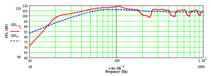
here is the difference in simulation output:
the other parameters I calculated as follows:
MJKing said:fd = remains the same as the single driver
Qtd = remains the same as the single driver
Vad = is twice the single driver value
ZVC = impedance is half if the drivers are wired in parallel
= impedance is doubled if the drivers are wired in series
Sd: the driver surface area was doubled
Bl : was also doubled to account for the longer length of wire present in the series connection
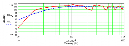
here is the difference in simulation output:
Attachments
Le would be half as seen by the amp but as far as the accoustic output goes my (uneducated) resoning would be:
Le relates to the force acting on the coil. You have doubled the area of a single cone and two coils so Le should be double.
Just a guess but I'd be interested to know if I'm right or wrong.
Le relates to the force acting on the coil. You have doubled the area of a single cone and two coils so Le should be double.
Just a guess but I'd be interested to know if I'm right or wrong.
Zvc = impedance is half if the drivers are wired in parallel
Zvc = impedance is doubled if the drivers are wired in series
These are the correct relationships for impedance. Wired in parallel enter Re / 2 and Lvc / 2. Wired in series enter 2 x Re and 2 x Lvc.
Martin
Zvc = impedance is doubled if the drivers are wired in series
These are the correct relationships for impedance. Wired in parallel enter Re / 2 and Lvc / 2. Wired in series enter 2 x Re and 2 x Lvc.
Martin
Martin, thanks for the confirmation.
btw: can I read somewhere in your theory papers how the coil inductance is in the model for the response?
btw: can I read somewhere in your theory papers how the coil inductance is in the model for the response?
btw: can I read somewhere in your theory papers how the coil inductance is in the model for the response?
If you look at Figures 2 and 3 in the Alignment Tables article you will see Re and Lvc in the acoustic and electrical circuit models. I have not done anything different from the original Thiele / Small models.
Henkjan,
please excuse that I ask a similar question for a different configuration:
MJK, I´m simulating three woofers (all connected parallel) stacked one above the other in a narrow H frame. Does the same apply as for the TL? Of course I need to triple were Henkjan is doubling. Is it ok to just triple Sd? There is no way to distribute Sd along the H frame height. The end areas will have the proper size of course. What about the Terminus width? Still the width for the single driver?
Rudolf
I´m simulating three woofers (all connected parallel) stacked one above the other in a narrow H frame. Does the same apply as for the TL? Of course I need to triple were Henkjan is doubling. Is it ok to just triple Sd? There is no way to distribute Sd along the H frame height. The end areas will have the proper size of course. What about the Terminus width? Still the width for the single driver?
Hi Rudolf,
For three drivers wired in parallel I would use the following properties.
fs = same as single driver
Qes, Qms, Qts = same as single driver
Re/3 = on third of the single driver
Lvc/3 = one third of single driver
3 Vas = triple the single driver value
BL = same as single driver
3 Sd = triple the single driver value
For the H frame geometry I would use the same width as the single driver and then triple the height, or if lying on its side the same height and then triple the width. The terminus area will be three times the value of the single driver H frame.
Hope that helps,
Martin
- Status
- Not open for further replies.
- Home
- Loudspeakers
- Full Range
- Le in MJKing mathcad sheets - 2 drivers