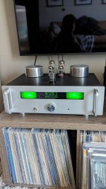
Hi Zdr,
I can see from Jacob's screenshot that his firmware version is 1.23G. What are the changes from the previous version 1.22G? Thanks
I can see from Jacob's screenshot that his firmware version is 1.23G. What are the changes from the previous version 1.22G? Thanks
Actually, the latest version is 1.29G, posted now. It has new remote subroutines, as the old ones just stopped working with latest updates. You will notice faster reaction to remote commands, especially for volume changing.
Hi, Great project.Source code is now posted to my google drive folder.
It's not just a simple matter of having a source code, you will need to know how to compile it. You need minicore lib for a start:
https://mcudude.github.io/MiniCore/package_MCUdude_MiniCore_index.json
Is it possible to share source code, with a community?
Hi Jacob,I am only able to get up to
400k on rt2\lsh and r4\rsh here are the measurements of of the LDRs. Any thoughts I'm relatively close to spec?
View attachment 1165476
What case are you using ?
- Dan
Hello ZDR,Are you trying to flash the board you got from me? Otherwise it won’t work.
I bought a kit of 2 PCBs from you in 2019, I just took the time to finish the assembly.
Unfortunately I made a big mistake and broke the arduino uno.
Is it possible to buy another one?
Thank you for your reply.
Sincerely
Thierry
Hi, ZDR,
You have done a great job with the LDR project! There is something that bothers me that you may be able to answer.
The LDR driver circuit has a MOSFET with a 220K gate-bleed resistor and a 20K trimmer resistor to the bias signal. At maximum trim value, the gate will be at (1 - 20/220) x 5V = 4.55V. That voltage should bias the FDV301N MOSFET on all the time, but no one has reported trouble with the circuit. What am I missing?
I appreciate your taking time to set me straight!
Sincerely,
- Guido
I ignored the 1K resistors in the gate filter? When there is no PWM signal, the input is pulled to ground so the gate has 220K in parallel with 2K, or 1.98K to ground. The 20K trimmer in series with the 2K-ish bleed resistor gives a minimum of about 0.45V at the gate, and can be increased with the trimmer. I think that is right.
- Home
- Source & Line
- Analog Line Level
- LDR Pre MkII - LDR volume control and I/O switching
