Confirmed RSE Ldr is dead, when I receive replacement, I will solder using high lead content solder and low temperature iron, in order do not burn the Ldr, which seems to be very sensitive.
I received all three LDRs from Farnell, but they test without reading before install.
On pcb I have removed the defective and two more since there is only one that measures optimal and I confirm those two still are healthy with readings.
Maybe the new ones on the circuit behave well. But no, they don't work either.
I'll have to buy back, this time to Digikey
On pcb I have removed the defective and two more since there is only one that measures optimal and I confirm those two still are healthy with readings.
Maybe the new ones on the circuit behave well. But no, they don't work either.
I'll have to buy back, this time to Digikey
Now I noticed, I had ordered a bare NSL-32, without further designation SR3.
Please Neb confirm this is cause not working. I would like buy again from Farnell.
Please Neb confirm this is cause not working. I would like buy again from Farnell.
Guess what, I just received SR3 after a long time of using SR2, and I had the same problem. It seems SR3 is a bit slower than SR2, so the test is too fast for them. Now I added a delay before test, and it should pass with both SR2 and SR3. New firmware uploaded, v22
FINALLY IS WORKING NOW!!
Updating firmware not work in my case. It seems I have one SR3 too much higher minimum resistance at 132R, that prevent fix error warning. I then bought a set of four SR2 and again same error warning. I then measure after adjusting to 750k, I got 262R, 324R, 252R and 84R. Obviously this last one is the only one healty, and I used it to replace the worse one (132R) from the SR3 lot.
My finally working set has all Ldr min res. below 100R ( 90R, 84R, 57R and 41R) and perform much better than stepped ladder 24 positions Dale resistors (Compared at same nominal impedance 10k). Basically less distortion at higher volume. Only complain is not possible finelly adjust the volume as too much dinamic and gain, so I can't exceed step three.
Maybe increasing impedance to 20k?
I set as output impedance the higher available 250k. Because is closer one to my preamp Salas dcg3. Wich has on input a 332k resistor to ground.
Yesterday I listened to the LDR with the 20k nom./50k load settings recommended for my preamp designer. before going down to the minimum 5k/50k.
To the worst. The large and dynamic scale disappears, but also the intoxicating and hypnotic sound, which may have been described as 'colored' or 'euphonic' by some LDR volume skepticals. With that was obvious the need to look for a midpoint.
Switching to 10k turned out to be a nightmare, as the recipe for three or four nano resets did not take further effect.
But I persisted, also doing bias adjustment cycles,
(which was always out of place) and the consequent half-hour calibration. After three hours or more I succeeded, I don't know if by chance, but just after reducing the bias to 700k of the pdf instead of the 750k of the discussion thread here.
All right, I can't complain about 10k nominal impedance, waiting to replace the defective LDR Pre MK2 (I don't even dare to turn it off) to continue with the task, going up and down slightly around 10k, to confirm with certainty the value.
Hello Zdr,
I have a small problem, I tried to flash an Arduino nano with an Atmel 328PB to put the program LDR_Pre_MkII_G_v1.22.hex following the procedure you gave but without success.
I noticed that I don't have the test.bat file in the firmware directory.
I have tried several times and on different USB ports but I always get the same error message that I give below:
"avrdude: stk500_recv(): programmer is not responding
avrdude: stk500_getsync() attempt 1 of 10: not in sync: resp=0x78
....
avrdude: stk500_getsync() attempt 10 of 10: not in sync: resp=0x78
avrdude done. Thank you."
Do you have a solution to my problem?
Thanks a lot
No, I tried to find a solution for a friend who has a broken preamp and I wanted to upgrade the software. Now, the preamp works but it still has a error 20 at startup. The power supplies are correct, the relays too. It is possible to make a calibration, but at the restart it has systematically the error 20. Maybe a problem with the ldr?Are you trying to flash the board you got from me? Otherwise it won’t work.
Which type of ldrs are you using? Slower ones had a problem with firmware being too fast on boot.
Hello, I am using the LDR NSL-32SR2.Which type of ldrs are you using? Slower ones had a problem with firmware being too fast on boot.
Now we don't have the error 20. But, we can't do the calibration because we have this error message: RSE too low,
But when I try to set the bias I can't go beyond 27,5 K for RSE and 370 K for RSH. No problem to set LSE and LSH to 700 K.
However the LDR values seem to be correct:
LSE= 61 / LSH=65 / RSE =53 / RSH= 64 Ohms.
When I measure the voltages in mode ajust bias , I found this values on the outputs D10 / D11 / D0 and D1 and I notice big differences:
D10=9 mV
D11=13 mV
D0=167 mV !
D1=75 mV !
Apparently the problem comes from the output voltages. In your opinion, what could be the cause of this voltage difference ?
Thank you for your answer
Hi, i have a couple questions
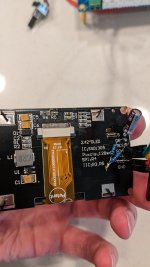
Outline of what I'm trying to do. I have 6SN7 tube rectified pre-amplifier (tubes for Hi-Fi SP14) . I recently purchased LDR pre-mark II (V1.31) pcb and microcontroller that I got from you. I would like to attenuate and control outputs of the active preamplifier with your passive. With added benefit of your cool user interface and remote!
My understanding I would have to do to integrate is use the connections located directly below the PCB boards version number. L-R out of ldr > L-R in sp14 >L-R out of sp14> L-R in ldr?
I see four separate grounds which grounds correlate to left out, left in, right out, right in? Or are they universal
For the power connections The through holes that are labeled 1 are grounds the 2 are power?
To control the power of the tube pre I could use the relay out into a non-latching 5 volt power relay?
Sorry for the barrage of questions.
Thanks Jacob
Hi,
1. all audio grounds are interconnected, so you can pick any.
2. relay out is low power, cannot drive any relay directly. If you try to connect anything that draws >40mA it will blow Arduino output. You need something like ULN2003 or a transistor.
3. you can use outputs below the version number, they are connected directly to LDR output and before output relays.
4. 1 are grounds, but always test before connecting power.

If you want to power the board with 4 separate power lines, there is no need to put smd voltage regulators on board.
Zdr thanks for the response! Much appreciated looks like it it's going to be a fun project.
Glad I did not try a 5 volt relay!!
Glad I did not try a 5 volt relay!!
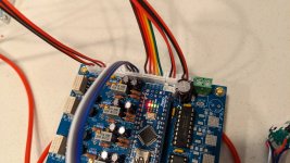
Any idea why I might not get the screen to turn on?
Looks like I'm getting 5 volts On outputs SDA and SCL. I'm not connecting the backlight out to anything?
The nano looks to be powering up just fine.
Looks like I'm getting 5 volts On outputs SDA and SCL. I'm not connecting the backlight out to anything?
The nano looks to be powering up just fine.
Attachments
I am only able to get up to
400k on rt2\lsh and r4\rsh here are the measurements of of the LDRs. Any thoughts I'm relatively close to spec?

400k on rt2\lsh and r4\rsh here are the measurements of of the LDRs. Any thoughts I'm relatively close to spec?
400k max or min? You should set it to around 700k as message says, and only during the message display. If this is not possible, something is wrong on that channel.
- Home
- Source & Line
- Analog Line Level
- LDR Pre MkII - LDR volume control and I/O switching