Yep, I also wondered what this is.
Window artefact? Spectral leakage?
Chris Daly, those are all probably very good points you made and I don't know what Pass used to measured them, but neither change how the impedance curve of each LDR is different.
Btw, I found another measurement on diyhifi.org. The "worst" one is this:

All the info provided is: "2V RMS input, -20dB attenuation, THD=0.74%".
Btw, I found another measurement on diyhifi.org. The "worst" one is this:
All the info provided is: "2V RMS input, -20dB attenuation, THD=0.74%".
Last edited:
Window artefact? Spectral leakage?
But then it would appear on all three, it looks (hard to tell for sure) that it is only on the red one. The literature confirms that CdS has predictable generation/recombination noise possibly far in excess of sqrt(4KTR) modulated by the current i.e. makes sidebands like a carbon comp. It is also possible that here the effect is negligible.
Ok. What exactly are the key factors here?
With LDR's we want to deliver current just to the anode and exit via
the cathode, and not give parallel resistance or capacitance or
combinations, any ability to become a false load.
Refer to Figure 10 and Figure 12 of the Silonex data
http://www.cresttech.com.au/pdf/Silonex/levelcontrol.pdf
Note the use of 2x 4148 diodes, and series current setting resistance,
for the series and shunt LDR's in Figure 12.
Note the power supply capacitance is in the cathode of the
series LDR, and the Shunt LDR has an added diode
for its cathode.
Capacitance multiplier circuits in earlier stages are a far better
way of delivering capacitance, in my experience
A single gang pot arranged to work in series to the LDR anodes, with its
lower arm to shunt and upper arm to series, similarly avoids any resistance
in parallel with anode and cathode.
Cheers / Chris
That would be great! Comparing different boards would be useful. Could you just send me a complete board that I could use for a while? What are the PSU needs for this?
PSU needs are: regulated 12 volts, and attention to star grounding
for the boards.
But then it would appear on all three, it looks (hard to tell for sure) that it is only on the red one.
Yes, it's hard to tell, you could be right. I wonder if it would be possible to plot each of them separately so that this could be pinned down?
Thanks mbrennwa, a set of tests around the -10/-15dB level would be very interesting, especially if the H3/H5 changed too ....
I'll chase up Nelson's work on this - a refresher and quite appropriate here.
You have one of Karl's production BTFS units?
Thanks Scott for the link - struggling with the feedback technique - will plod on.
The take away is that an excess noise mechanism proportional to current (signal) dominates below 10kHz.
Would this 'noise mechanism' have any connection to the levels of the H3 and H5 distortion?
Also, theoretically anyway, as the 2 devices interact (series and shunt) in a complete volume control, there would be a level of attenuation that would produce the lowest noise, yes? And possibly, a corresponding lower level of H3/H5 also?
And could 'all this' be connected to the anecdotal comments that transferring a > 2 volt signal through the Siliconex devices will produce audible signal degradation?
Yeah, in hindsite, should have kept my fingers otherwise engaged - my apologies, Daniel
No need to apologize to me! I was hoping to calm the situation and steer it back towards some learning, and you grabbed a hold of that, which is good. 🙂
It's OK, I'm a big boy. 😀
Rest assured, I wasn't worried. 😀
No problem!
An interesting thing about that posted test by 'mbernnwa' -
I don't have any problems about additional H2 in my home system but I doubt that I'd ever consider the possibility of intentionally adding a fair quantity of H3 - and now I find I've not only done just that, but that I prefer the effect!
I guess this kills off any pretensions I might have had to ever become some sort of audiophile!
You do learn something each day, eh - this one's just been a bit slow in coming!
You seem to be mixing up LED drive/control current with LDR audio current.With LDR's we want to deliver current just to the anode and exit via
the cathode, and not give parallel resistance or capacitance or
combinations, any ability to become a false load.
Refer to Figure 10 and Figure 12 of the Silonex data
http://www.cresttech.com.au/pdf/Silonex/levelcontrol.pdf
Note the use of 2x 4148 diodes, and series current setting resistance,
for the series and shunt LDR's in Figure 12.
Note the power supply capacitance is in the cathode of the
series LDR, and the Shunt LDR has an added diode
for its cathode.
Capacitance multiplier circuits in earlier stages are a far better
way of delivering capacitance, in my experience
A single gang pot arranged to work in series to the LDR anodes, with its
lower arm to shunt and upper arm to series, similarly avoids any resistance
in parallel with anode and cathode.
Cheers / Chris
PSU needs are: regulated 12 volts, and attention to star grounding
for the boards.
Which are you referring to?
Yes, it's hard to tell, you could be right. I wonder if it would be possible to plot each of them separately so that this could be pinned down?
It really is the LDR only. No such signals apparent with the pot or fixed-resistor divider. Sorry, I am too lazy to replot everything right now to make this clearer. I will take care of this later, when I do the measurements.
You have one of Karl's production BTFS units?
Yes. I also have an OptiVol, and Chris Daly offered to provide one of his attenuators for testing. Any suggestions for other designs that should be included in the tests? I'd like to gather everything on my bench and do all the measurements at the same time.
You seem to be mixing up LED drive/control current with LDR audio current.
Which are you referring to?
Hi Andrew
Referring to LED drive/control.
Cheers / Chris
It really is the LDR only. No such signals apparent with the pot or fixed-resistor divider.
Good enough, Scott's right, no need for any more work from you. Many thanks!
Hi mbrennwa,
I think they'll all mostly exhibit a quite similar H3/H5 test result as the harmonic characteristic is a part of the LDR device itself - the different control methods won't have much effect, I think, unless the impedance settings cause a different level of H3.
And, as Scott indicated with the NASA link about relative device noise, if the signal voltage (and current) level and attenuation level alters the H3 content .... - this is indeed speculating with little facts, but the possibilities are intriguing
I've got one of Karl's original prototypes with a few slight mods, and it sounds nearly identical to Alan Flores Warpspeed kit version - these were the 'best' sounding volume controls that I've heard in quite a few systems that were tried and quite a few headphone amplifiers - very subjective opinions, I'm afraid
Uriah's LighterNote may show something different as you can adjust the series impedance independently of the shunt impedance, hence varying the total unit impedances, that may alter the level of H3/H5 also - it's also a CCS method (current control)
The ZenMod version (Poor Man's Serbian ...) is a development of the early current control version by Peter Roodzant, as per the LightSpeed Thread post #1000 (stuck in my mind!) but I expect this to have a similar H3 characteristic to Uriah's as they both work in a similar way
Uriah's new one uses a single LDR as the series device and a set of indirectly switched shunt resistors (23 stages) - as it has just the single LDR, maybe this will have a lower H3 signature - it hasn't arrived yet.
I have one of Chris' units but as I use a conflicting earthing system, couldn't fit it to my system without problems with loops
The computer based control mechanism has changed the accuracy, flexibility, impedances, operating conditions and so forth, but the actual LDR devices are the same for nearly all the versions, so I would expect a similar H3 behaviour to all - not sure about the Arduino based version.
Hope this helps ...
H2, H4 etc. don't appear because of LDR symmetry. H7 and above are below the measurement threshold.jameshillj said:From this graph, if I've got this right, there's about 0.4% H3 at 27dB attenuation and the pot has about 0.05% at same attenuation, and similar difference for H5 (a bit surprising that there no other H's).
You may find that Chris has his own unique approach to designing circuits.mbrennwa said:Ok. Why (again)?
See, for example:
Chris seems to think that the audio signal quality on the LDR is somehow sensitive to the details of the LED current drive circuit. All that is actually needed is the right currents delivered with low noise and hum. The diodes are merely there to get the volume change law right.Chris Daly said:With LDR's we want to deliver current just to the anode and exit via
the cathode, and not give parallel resistance or capacitance or
combinations, any ability to become a false load.
Refer to Figure 10 and Figure 12 of the Silonex data
http://www.cresttech.com.au/pdf/Silo...velcontrol.pdf
Note the use of 2x 4148 diodes, and series current setting resistance,
for the series and shunt LDR's in Figure 12.
Note the power supply capacitance is in the cathode of the
series LDR, and the Shunt LDR has an added diode
for its cathode.
Capacitance multiplier circuits in earlier stages are a far better
way of delivering capacitance, in my experience
The LDR excess noise is in addition to distortion.jameshillj said:Would this 'noise mechanism' have any connection to the levels of the H3 and H5 distortion?
My guess is that lowest distortion will come at -6dB attenuation, as this minimises the signal voltage across the LDRs. This may also give minimum excess noise.Also, theoretically anyway, as the 2 devices interact (series and shunt) in a complete volume control, there would be a level of attenuation that would produce the lowest noise, yes? And possibly, a corresponding lower level of H3/H5 also?
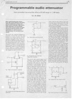
I vaguely remembered doing some tests with LDRs many decades ago. I dug out the first page of an article I did for (then) Wireless World, see attached. 1980. According to what I wrote then I decided not to pursue it due to .. too much noise.
Jan
Jan
Attachments
Last edited:
Thanks Scott for the link - struggling with the feedback technique - will plod on.
The take away is that an excess noise mechanism proportional to current (signal) dominates below 10kHz.
Would this 'noise mechanism' have any connection to the levels of the H3 and H5 distortion?
No the noise is an independent phenomena but both are signal amplitude dependent, and sorry the circuit described in that link may not be relevant I posted it as a source for the noise discussion. Also I would think that noise at 15k - 20k on the plots posted here has an external origin.
I vaguely remembered doing some tests with LDRs many decades ago. I dug out the first page of an article I did for (then) Wireless World, see attached. 1980. According to what I wrote then I decided not to pursue it due to .. too much noise.
Jan
Please take this is spirit of open speculation. The low frequency noise modulation and low order distortion (.5-1%) bear certain similarities to common vinyl artifacts.
It would be nice to see the output spectrum given a 50 Hz instead of a 1 kHz input signal. Given that they seem to be nonlinear in almost any conceivable way...
Last edited:
Could the sound of an LDR volume control be improved by a little 0.45Hz AC in the LED feed current?scott wurcer said:The low frequency noise modulation and low order distortion (.5-1%) bear certain similarities to common vinyl artifacts.
- Home
- Source & Line
- Analog Line Level
- LDR Attenuator Impressions