Hello all,
I must make this quick: what is the way to determine the proper ratio of inductance to capacitance when making an audio bandpass filter (1 st order, either series or parallel)?
Thank you!
I must make this quick: what is the way to determine the proper ratio of inductance to capacitance when making an audio bandpass filter (1 st order, either series or parallel)?
Thank you!
With a capacitor and an inductor, it isn't a 1st order filter, but a second order one.
Basically, the L/C ratio is the analogue of an impedance², which has to be compared with the load.
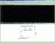
This sim shows the effect of an increasing L/C ratio, beginning with the green trace.
If you extrapolate to infinity, the circuit will become just a big inductance and a tiny capacitor, both having extremely high impedances at the frequency of interest, and allowing very little signal through, giving an extremely sharp peak.
This analysis neglects the Q of the reactive components themeselves.
Attachments
- Status
- Not open for further replies.
