If you're going to try and reverse engineer it why don't you at least buy a couple modules?
Are you doing this just for your own personal gain?
Are you doing this just for your own personal gain?
First of all, this whole thing is more or less for fun, second I don't need phisical object which is also epoxy sealed (if I have good pic there is no differnce to real one), and finally I don't have time currently to deal with these due to studies obligations....
but I wanted to help, if you just want to sell this as a cheap junk thats different thing ...
but I wanted to help, if you just want to sell this as a cheap junk thats different thing ...
Hey, I just read of someone losing their feedback resistor on a chip amp and it put full DC on the outputs...is this possibly the issue with these modules? Where is the Feedback resistor anyway?
SO I am reviving this thread - I am quite sure I mistakenly mixed up the Power Ground and Negative supply when I saw smoke.
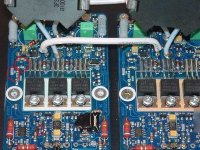
As far as the MOSFETs, the following numbers are shown on my DMM in DIODE mode MOSFET #1 is to the right ao the V+ Side of the amp module)
MOSFET #1 GATE - SOURCE - 759
MOSFET #2 GATE - SOURCE - 731
MOSFET #3 GATE - SOURCE - OVERLOAD
Does this mean MOSFET #3 is likely blown, or maybe MOSFET #1 & 2 are blown? Doesn't seem to be a short anywhere on either MOSFET (none of the legs shorting to each other)
Also, These are IRF640N and supposed to be IRFB31N20, correct (ZAP V 2.1 Standard)
upon putting +/-20VDC on the rails, I get the following:
MOSFET #1 Drain to Source -14V
Drain to Gate +14V
MOSFET #2 DRain to Source -24V
Drain to Gate +24V
MOSFET #3 Drain to Source 0V
Drain to Gate 0V
MOSFET #1 is on V+ side of module.
And I am getting a consistent 5V on the output.
Like I said, I am pretty sure I accidentally mixed up the -V Rail and Power Ground
Any clues? Anything look wrong? I just bought six IRF640N to replace some/all of the MOSFETS and should be here in a few days...
OK, so I noticed a fried 1K resistor in front of the -V side cap, replaced it and now have the following:
upon putting +/-20VDC on the rails, I get the following:
MOSFET #1 Drain to Source -14V
Drain to Gate +14V
MOSFET #2 Drain to Source -24V
Drain to Gate +24V
MOSFET #3 Drain to Source -20V
Drain to Gate +20V
DMM in DIODE mode MOSFET #1 is to the right and the V+ Side of the amp module)
MOSFET #1 GATE - SOURCE - 614
MOSFET #2 GATE - SOURCE - 613
MOSFET #3 GATE - SOURCE - 615
But I still have +5VDC on the Outputs...
Zkaiser -
In Post #19 I showed the SMD resistor that was fried - I had some one say 20k and someone else say 1K...
Do you know what it is?
Appreciate the help...never was able to get that hi res digital pic for you...
In Post #19 I showed the SMD resistor that was fried - I had some one say 20k and someone else say 1K...
Do you know what it is?
Appreciate the help...never was able to get that hi res digital pic for you...
Hi
Send them too me, I will post them + I like those kind of pictures 😀. My email is down here...
|
|
V
Send them too me, I will post them + I like those kind of pictures 😀. My email is down here...
|
|
V
I have this picture which leeds me to think that this resistor value is, let's say about 1.6ohm with 1% tolerance (black blue gold brown) which is very reasonable value to burn at this power rating (1/4W)...
PS
If anytime you find some way to shoot hi res pictures I will be glad to see them.
PS
If anytime you find some way to shoot hi res pictures I will be glad to see them.
Attachments
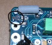
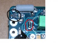
Yes, a transistor - I didn't look closely at what was in the ring - just saw the ring in the wrong spot...
I see another resistor (R14 and R16) by the MOSFETs with color of Grey/Black/Blue/Gold/Brown.
It measures 82ohms on the board...I am really confused now...
Either way, a 1K Ohm or a 1.6 Ohm did not stop the + 5V Offset - it shows the exact same resistance.
As I said, I have +/- 20VDC on rails....which is lower than what they advise (+/- 32VDC is min according to data sheet)...could the lower voltage rails be a reason there is an offset?
FETS are not shorted, all major caps and all large resistors on the perimeter all seem to be OK too...
Well I just put 35VDC on the rails and got -35VDC on the outputs. Blue LED came on.
Back to square one.
Back to square one.
John65b, i will try to help you if i can.
The resistors in question are 80.6 Ohms. So 82 Ohms seems to be fine.
Did you have a load on the output at startup?
Did you measure the voltage on the input op-amp? Pin 4 should be -4.5V and pin 8 should be +4.5 referenced to GND.
Also check the 2.2 Ohms power resistor at the input side for open circuit. It's a GND connecting resistor, so you can just use you ohm-meter from input GND to output GND, and check for connectivity ~ 2 Ohms.
I hope it helps.
Also check the 2.2 Ohms power resistor at the input side for open circuit. It's a GND connecting resistor, so you can just use you ohm-meter from input GND to output GND, and check for connectivity ~ 2 Ohms.
Input GND to output GND is 2.7 ohms, so OK here.
Did you have a load on the output at startup?
I initially had no load across the output and no load on input and powered up...full -35VDC on output
I put a 8 ohm load resistor across the output and still had around -20VDC at output.
The resistors in question are 80.6 Ohms. So 82 Ohms seems to be fine.
I currently have one module with a 1/4 watt 1K ohm resistor, and the other with a 1/4 watt 1 ohm resistor.
I can put the correct 80 ohm resistor in place, but wonder if the issue is somewhere else, since both modules are having DC on rails still with resistor higher and lower than the required 80 ohm....I will put it in anyway and re check the outputs.
Seems with this resistor out, the MOSFET is wide open
Did you measure the voltage on the input op-amp? Pin 4 should be -4.5V and pin 8 should be +4.5 referenced to GND.
Measured -4.8V on pin 4 and +4.85 on pin 8 referenced to input GND, so OK here too...
- Status
- Not open for further replies.
- Home
- Amplifiers
- Class D
- LC Audio Zappulse 2.1 Issue