Hello all,
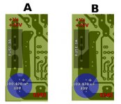
I'm trying to design a pcb layout for Elvee's Circlophone amplifier. I want to place fuses on PCB and followed by bypass capacitors regarding to the current flowing direction. I want to make sure bypass caps are visible to the circuit so, I draw U shaped traces as shown in layout "A" for ensuring the current flow over the bypass capacitor. I wonder if this principle is practical and advantageous comparing to the "B" one which is same layout in theory but doesn't convince me for real conditions. For the theory, current must be follow the shortest path thus, bypass cap could remain as misled in "B".
What do you think?
Thanks.
Attachments
Last edited:
It should be as in A, as B will give you noise/hum and is not correct.
Gajanan Phadte
Thank you Gajanan for the comment. I was already on "A" side but I was in need for some confirmation.
The full layout can be seen on link below. Any comment are welcome.
http://www.diyaudio.com/forums/soli...ssories-beginner-friendly-27.html#post3490468
Regards.
B is better, of course, simply because there's more copper and thus less resistance in general.
Why?
Because that copper "island" which connects Fuse+bypass cap+rest of the circuit is "equipotential" meaning "all its points are at the exact same voltage" meaning "connecting anywhere is the same" meaning all relevant connections (fuse/cap/amp) are the same as if they were twisted together and surrounded in solder.
This kind of weird ideas come from abuse of the "hydraulic analogy" where current flow is explained by imagining it's "water along a tube" which confuses more than it explains, because
a) water has mass ; electricity does not.
b) water has "low" velocity, so it passes by a point "before" it passes another, further away ; electricity has infinite speed and "gets everywhere at the same time"
c) different points of a mass of water can move away from each other or have different speeds ; electricity moves "instantly".
Before somebody nitpicks about speed of light, inductance, etc. , that becomes significant when parts are far away and connected through long and thin wires, not the case here.
Yes, putting that bypass cap 3 feet away, connected with 1mm wire can bring some problems, either at high frequencies where inductance becomes significative, or because wire resistance (specially at the ground return) can start to bother .... but not in a 1" x 1" copper "island", where maximizing copper is best.
Yes, the cap *will* be "visible" to the amp.
- Status
- Not open for further replies.