Hello All! Hopefully you will be able to help me out with a problem I am facing.
I am currently building 5.1 system. All the modules are in my possession and so is the case. I just have to think of a very good layout because the number and size of the modules is just stretching the limits of the case.
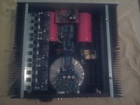
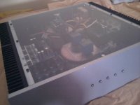
Heere are some photos of the mock assembly.
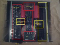
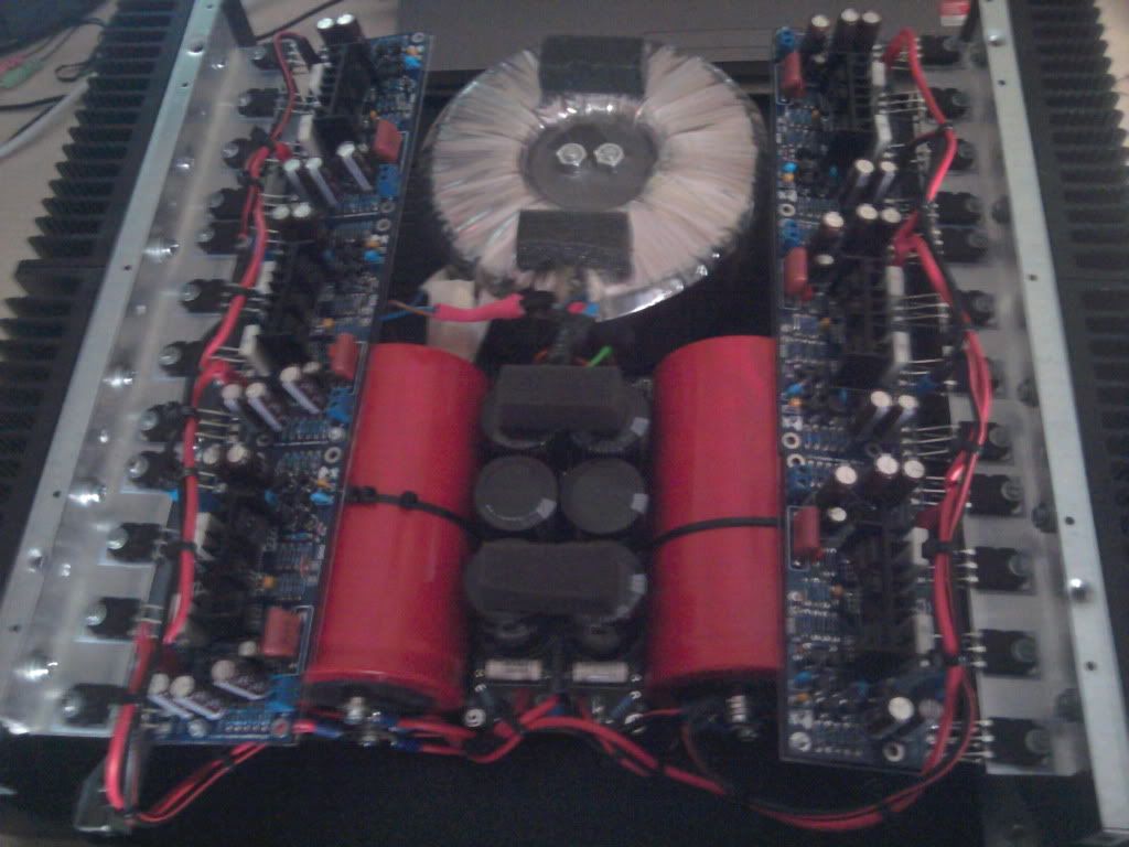
THe back panel was drilled for another project so don't considers it... Here is a photo with the name and function of all the modules :
Under the preamp there is the initial rectifying board and caps. The red large 40000uf caps are actually oriented in the toher direction so that from the terminal I can feed the 2 AMP "strips" in series.
Basically a midlle bridge made of lexan will support the DC protect modules and allow for a symmetrical build.
On the left we have a toroidal (small 30/40W unit) close to the power lines. So will be the softsart module (but on the right).
Could this work? Arethe modules in the right place? Do you forsee any problems in terms of hum, hiss and buzz from power lines?
I already have tried a similar configuration in another smaller build
To keep everything simple the LCD will hang from the lexan lid.
Thanks!
I am currently building 5.1 system. All the modules are in my possession and so is the case. I just have to think of a very good layout because the number and size of the modules is just stretching the limits of the case.
Heere are some photos of the mock assembly.
THe back panel was drilled for another project so don't considers it... Here is a photo with the name and function of all the modules :
Under the preamp there is the initial rectifying board and caps. The red large 40000uf caps are actually oriented in the toher direction so that from the terminal I can feed the 2 AMP "strips" in series.
Basically a midlle bridge made of lexan will support the DC protect modules and allow for a symmetrical build.
On the left we have a toroidal (small 30/40W unit) close to the power lines. So will be the softsart module (but on the right).
Could this work? Arethe modules in the right place? Do you forsee any problems in terms of hum, hiss and buzz from power lines?
I already have tried a similar configuration in another smaller build
To keep everything simple the LCD will hang from the lexan lid.
Thanks!
Attachments
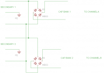
The bridges are 35A ( KBPC3510)
I did not fully understand your post... (my bad..running a slight fever 🙂 )
Is there a real drawback in using the bridges' outputs in parallel? The load would be evenly spread across the 2 bridges and back to the transformers if the capcitor banks are connected in parallel would it not?
Anyways...here is a small picture..hopefully it is clear enough to show what I mean..
http://i365.photobucket.com/albums/oo98/Alexontherocks_2008/bridge.png
Disregard last post.
You can do this (attached), and each channel will still be seperate, while not being dual mono strictly. I am still waking up this morning.
EDIT: corrected
OK, we're OT. I got your PM. Sorry.
Attachments
Last edited:
The red large 40000uf caps are actually oriented in the toher direction so that from the terminal I can feed the 2 AMP "strips" in series.
You don't mean that you are going to connect amplifiers in series somehow, do you?

nono...I mean all the vcc+ and vcc- per side will be conencted to a common "rail" stemming from the final 40000uf capacitors..
I am concerned about the DAC being right on top of the transformer. Can it be an issue?
I am concerned about the DAC being right on top of the transformer. Can it be an issue?
It's not a good idea to have PCBs for audio above or below a toroidal transformer like the DAC in the picture, that area is where the strongest magnetic flux leakage radiates, it could induce hum.
Mike
Mike
If your really stuck you could put the transformers in another box.
Leave the smoothing caps and bridge rectifier in the amp housing.
Leave the smoothing caps and bridge rectifier in the amp housing.
I had the doubt.....I guess an external DAC is required then. Actually I was looking for a 5.1 USB decoder with some decent aesthetics. Suggestions? 🙂
I have another question.. How can I effectively have low/high input sets?
What I mean is that I would like to have 2 groups of RCA connectors. One group leads to the the preamp, and the other set leads directly to the AMP. Can this be achieved without an input selector? Is it as simple as having the leads from the preamp and from the RCA meet at the amplkifier input connector?
Sorry for the dumb questions...trying to figure this one out methodically 🙂
If I understand your question, you could add a set of "Pre-out" and "Main-in" jacks and strap them together with short interconnects until you want to use them.
Mike
Mike
Could you mount the board perhaps vertically somewhere else and run shielded wires well routed to the connectors?
what I meant is.....
I might add an external usb decoder for 5.1 . In this case the signal need not be preamplified by the board inside the amplifier (the red board close to the front panel).
So I am looking for a clean way to have 2 sets of RCA inputs in the back:
1) that gose directly to the preamp
2) that gose directrly to the amp modules (high input from the decoder)
can this be done cheaply? How?
Thanks!
I'm still not entirely clear what you're asking about the RCA jacks. Do you want a pair of jacks that come from the outputs of the preamp, and another pair that go to the power amp inputs so that something like an equalizer can be inserted there? If so, just add four RCA jacks to the rear panel, two to the preamp outputs and two to the poweramp inputs and use short interconnects to make the connection when you don't have anything plugged in there.
Mike
Mike
Here is a stupid schematic ade with paint 😛
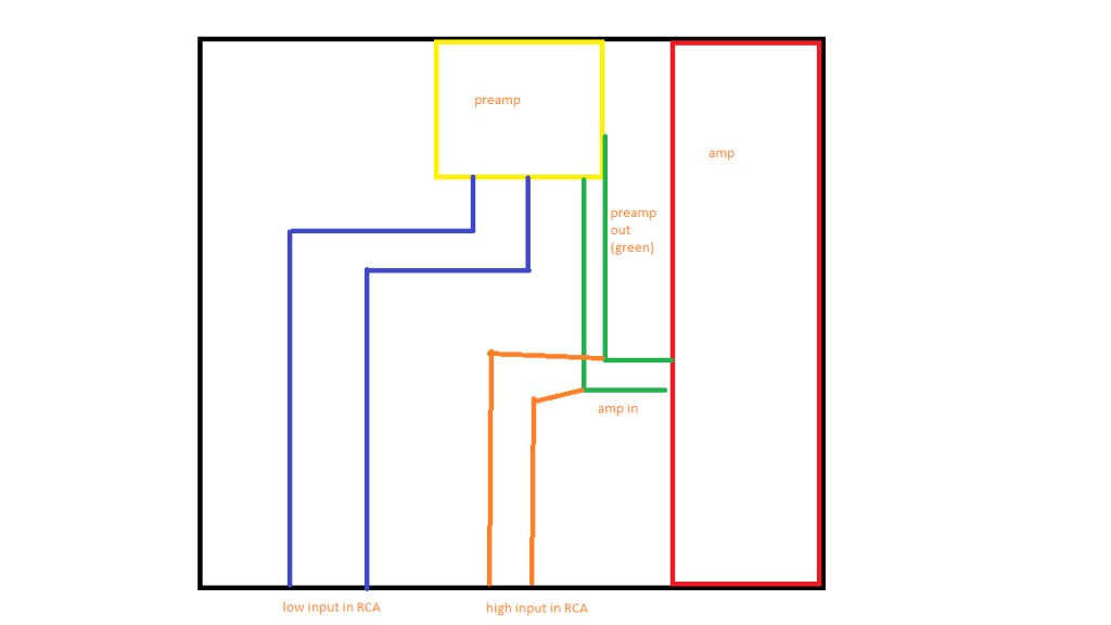
the blue lines are the preamp input....the orange the "direct" amp input (bypassign the preamp).
I just have a problem with the junction point (where green and orange meet). Must I use input selectors? Can I simply join the two leads (from the preamp and from the "high level" input directly at the signal in connector on the amp?
Thanks!

Here is a stupid schematic ade with paint 😛
the blue lines are the preamp input....the orange the "direct" amp input (bypassign the preamp).
I just have a problem with the junction point (where green and orange meet). Must I use input selectors? Can I simply join the two leads (from the preamp and from the "high level" input directly at the signal in connector on the amp?
Thanks!
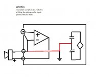
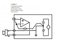
I'm afraid that the "high rca input" (orange) would see a weird impedance, would it? (amplifier + preamp output) since it is directly connected to preamp output (green).
Need some kind of source switching. Rotary switch? Small relays controlled by buttons?
Sorry for the late response. I have redesigned the amp to have only a preamplified input. I have tested the modules qith the preamp and they checkout for simple TV/movie use.
Here are some pics of the power rail assembly.
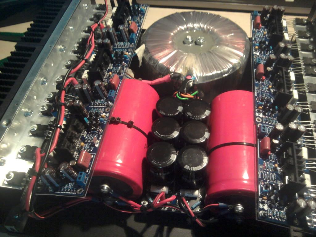
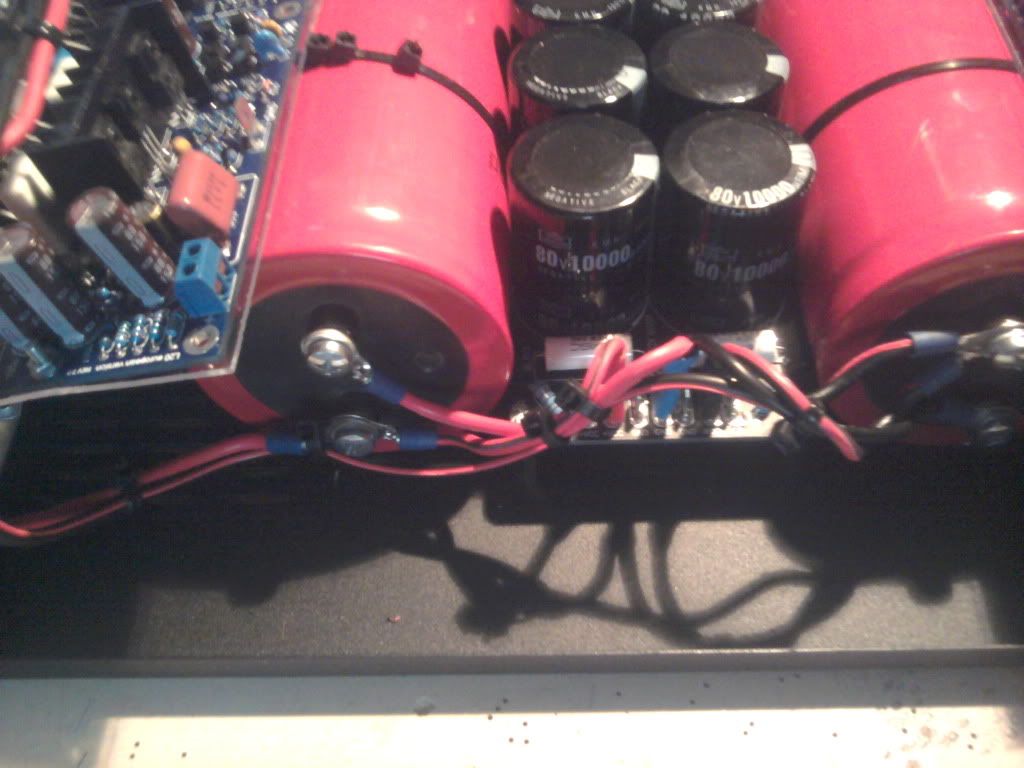
I only have a doubt.
The amp modules have a "ground" connection. Should I ground this connection to the common central capcitor banks' ground or should I "star ground" it like in a star design?
Thanks!
Here are some pics of the power rail assembly.
I only have a doubt.
The amp modules have a "ground" connection. Should I ground this connection to the common central capcitor banks' ground or should I "star ground" it like in a star design?
Thanks!
- Status
- Not open for further replies.
- Home
- Design & Build
- Construction Tips
- Layout problem. 5.1 system PREAMP DAC etc