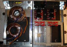
1st post and finally took the plunge. Was hoping some of the more experienced builders could offer some advice on where I should assemble the internals to my GC. Mostly the amp Brds and the power supplys. I have looked thru the gallery and got the basics. The enclosure is from an old series 1 TIVO unit that I gutted.
I have a Dual Mono Block setup from BrianGT. Two 250v xformers 2x25v which will be powering a pair of Klipsch Ref IV RF62's.
Thanks to BrianGT and this great DIY forum.
-BB
I have a Dual Mono Block setup from BrianGT. Two 250v xformers 2x25v which will be powering a pair of Klipsch Ref IV RF62's.
Thanks to BrianGT and this great DIY forum.
-BB
pretty goofd
Hey that is pretty good.
I cannot tell where your input/output connectors are going? On the top? (I will assume).
I would swap locations of chip boards and the PS Capacitor boards. Your output is on the back/top right? So put the PS Cap boards on the front and the chip boards on the back.
This will keep the AC away from your amplifier boards.
Are you going to use the fan?
Yes that's a excellant idea thx. Not sure if I will use the fan. Is there 12v I can tap off of without interfearing with the circuit?
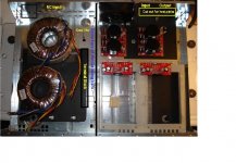
New pic with input/output labeled. I want to cut out the back under the input/outputs for the heatsink for the amp Brds.
Thx... -BB
New pic with input/output labeled. I want to cut out the back under the input/outputs for the heatsink for the amp Brds.
Thx... -BB
Attachments
Seems like a waste not to use the fan since its already there. You could use an LM317 12 volt regulator (use heatsink on it!) to get 12 volts from your + supply. Or smaller voltage to make the fan quieter. Or make an adjustable voltage circuit as shown on the data sheet.
Or you could make a temp sensing circuit using a bistable switch (Mouser part 802-STC-120, here). Put the switch on the heat sink and use it to automatically flip on the 12V power when the heat sink gets too hot (it closes) and flip it off when the sink cools off (it opens).
Or you could make a temp sensing circuit using a bistable switch (Mouser part 802-STC-120, here). Put the switch on the heat sink and use it to automatically flip on the 12V power when the heat sink gets too hot (it closes) and flip it off when the sink cools off (it opens).
Awesome idea. Thanks for the link and especially your time. I checked out your website. Nice stuff!
It's funny because I have done some of the same mods you have including the corner base traps (using 3 24" insulation rolls stacked) and the same acoustic treatments for my walls in the theater.
I think the fan is a must since I"ll have around 34v for rail voltage so the chips may get a little toasty.
-BB
fan
Yeah, I got a room with a bunch of dorky stuff all over it. It used to be ultra high end audio - Wilson Watt/Puppy, Goldmund Mimesis, Wadia, Cary, sonic frontiers, Balanced Audio Technology, and now its mostly all DIY. A lot more fun to listen to your own stuff.
If you use an LM317 to drop the voltage be advised that going from 36-12V will cause it to get quite hot (its limit is a 40 volt drop so you should be fine), make sure to put a good size heat sink on the regulator. Those little bast**rds get hot!
Will do thanks. Your so right about listening to your own stuff especially knowing you didn't spend a fortune and you have great sound!
I have another question if you don't mind. I have Avel Y23 xformers and the schematic on the side of it is not making much sense. Should probably call it a night.
Here is the data sheet scroll all the way to the bottom.
http://www.partsexpress.com/pdf/avelspecs.pdf
I'm hooking it up 115v. If i'm reading it correctly I should tie Blue and Violet together (neutral) and Brown and grey together (Hot) right?
I'll need to tie the second xformer to these same connections so it's fed the same I think.
Input: for 110 volt
Blue and Violet neutral
Brown and Gray line
Output:
Red AC to rectifier
Orange AC to rectifier
Yellow and Black to ground😀
or
Output
Black AC to rectifier
Yellow AC to rectifier
Red and Orange to ground
Thanks... BB
Hey man, you saw the web site! Look at the Picture and Picture.
blue and viloet get tied together to AC in
brown and gray get tied together to AC in
It is AC so does not matter which is line and which is neutral.
Red and orange get tied together to ground
Black goes to the rectifier
Yellow goes to the rectifier
Good thing I used an Avel too.
primaries get tied together on the AC input side, same coloring and connections.
Yeah I saw those exact pics but just wanted to be sure before I burnt something up. 
hopefully have it wired up by this evening. I post some pics.
Thanks 🙂
hopefully have it wired up by this evening. I post some pics.
Thanks 🙂
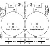
ok now I can't seem to figure out the secondaries. It's not clear in your picture where the wires go and I have 2 rectifier brds.
I am using two rectifier/PS brds. I have the chipamp PS brd. that has (2) AC1 and (2) AC2 connections.
Acording to my xformer schematic shouldn't I use blk/orng to AC1 and red/yellow to AC2?
thanks
-BB
I am using two rectifier/PS brds. I have the chipamp PS brd. that has (2) AC1 and (2) AC2 connections.
Acording to my xformer schematic shouldn't I use blk/orng to AC1 and red/yellow to AC2?
thanks
-BB
Attachments
Just wanted to give an update.
Received replacement toroidal transformer and used the light bulb 😉 and all was well. Both secondary voltages were good. Hooked it up to amp brds and tested my cheapy speakers then on to my main speakers.
I'm impressed with the sound compared to my old ONKYO M-5140 100W 2ch AMP which actually was not too bad.
Unfortunately I have the dreadful "Hum" coming through the speakers.
I think I will start a new topic for this hum issue with the details. I have done alot of searching and reading and tried various remedies to no avail.
Thanks everyone for your help!
-BB
HUM
If you have HUM problems and you have followed chipamp.com instructions to build the amplifier, first of all you must probe is to use shielded AC cables, shielded RCA cables and to connect the amplifier, preamplifier (if you have it) and cd player to the same wall outlet.
If you have HUM problems and you have followed chipamp.com instructions to build the amplifier, first of all you must probe is to use shielded AC cables, shielded RCA cables and to connect the amplifier, preamplifier (if you have it) and cd player to the same wall outlet.
- Status
- Not open for further replies.
- Home
- Amplifiers
- Chip Amps
- Layout advice for my 1st GC.