Hi, I have a few questions on fixing the phase changes that a crossover creates using lattice filters.
Can you connect multiple lattice filters together to get greater maximum phase difference? For example if X is a lattice filter, X X X R_load.
Do you calculate the lattice filters for R_load regardless of how many there are?
Can you connect multiple lattice filters together to get greater maximum phase difference? For example if X is a lattice filter, X X X R_load.
Do you calculate the lattice filters for R_load regardless of how many there are?
You can definitely cascade a number of latice filters together. I assume you are talking about the style where the 2 capacitors are a straight link and inductors are a crossover link (or vice versa). One latice group gives a 180 degree phase flip and the group delay that goes along with it.
As to impedance effects of a multiple string, I would give a qualified yes to using the end resistor as a calculated load all the way through. I haven't actually built or simulated a multiple, but I think that a single lattice looks resistive at the input. If that is the case then you are good to go because a latice plus resisitor is a resisitor, so 2 latices plus a resistor is still a resistor, etc. etc.
It would be good to try and simulate it just to be sure. That may be difficult since a lot of simulators like 3 terminal layouts (ladder networks). Perhaps someone else has played with that?
David S.
What are we trying to acheive?
_-_-bear
The latice is a pure all-pass, so phase shift or time delay.
http://en.wikipedia.org/wiki/Lattice_phase_equaliser
Last edited:
What I'm trying to do- fix the phase part of the transfer function caused by the crossover. My ultimate goal is to have a N-way speaker that has perfect impulse response. For example in a 2-way, if you make sum(magnitude(frequency response)) flat via a simple 2nd order crossover, then next up is making the phase for both 0. Then the transfer function for the system will be ideally 1 for the audible frequency range.
That's what everyone wants.
Best to not try to do it in passive, though... therein lies the rub... "n" active elements added to the signal path... and you can't really correct everything.
In DSP it starts to get really possible, but then you have inserted "n" DSP active elements in the signal path... which is starting to get closer to transparent. But beyond my ability to engineer, even if it can be made transparent. 🙁
_-_-bear
The best that you could achieve is time-alignment to some degree, but I doubt that you could achieve perfect impulse response with these when used within a passive crossover.
You could actually do group-delay equalisation (that's what they were originally intvented for actually !) with these passive allpasses but this would give high losses. So it is best done on the low-power side of things. There is one Swiss manufacturer of active studio monitors that uses group-delay equalisers. But they are made with active 2nd order allpass sections in front of an active crossover:
PSI AUDIO: Technology CPR:Compensated Phase Response system, providing a constant group delay response
Regards
Charles
You could actually do group-delay equalisation (that's what they were originally intvented for actually !) with these passive allpasses but this would give high losses.
Regards
Charles
Why is this? We are talking about unity gain all-passes.
The real issue is circuit complexity required. It may not be practical but it certainly is possible.
David S.
Do you really assume that this will end up without losses ? Apart from that: They would have to be terminated correctly in order to have the proper Q-values. This is not goint to give low losses either.
And it is definitely not possible to achieve a perfect step- or impulse- response by applying a delay line to one of the branches of a crossover. This way one can achieve what is called a time-aligned crossover but not a transient-perfect one.
What is possible is the use of a group-delay equaliser using allpass filters. But this would have to be placed in front of the whole crossover. For a second order crossover at 2 kHz one would need at least three 2nd order allpass sections in order to achieve a relatively flat group delay up to 20 kHz using such a method. I don't think that thi swould have a positive effect on driver dampinh however .....
Regards
Charles
Passive or active, it's the same to me. I haven't modeled it yet, but can you change the slope of the all-pass filter without changing the Fo?
Allpasses with a higher Q value "turn the phase faster" than those with a higher Q value.
The phase shift of an allpass is twice that of a lowpass with the same Q and pole frequency BTW.
Regards
Charles
The phase shift of an allpass is twice that of a lowpass with the same Q and pole frequency BTW.
Regards
Charles
Is there any concern with energy storage with certain combinations of components? For example where the choice of C/L would coincidentally produce a high Q if used as a second order filter. To put it another way, how would energy around the crossover contribute properly if it is ringing, and therefore too late for the other driver it is crossing to....or, is there such a thing as too high a Q in a lattice filter?
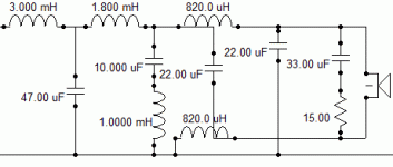
If it helps, this is the circuit I'm working on at the moment. By the way, it doesn't sound as bad as it looks.
If it helps, this is the circuit I'm working on at the moment. By the way, it doesn't sound as bad as it looks.
Attachments
- Status
- Not open for further replies.
- Home
- Loudspeakers
- Multi-Way
- lattice filter question