Tube_Dude said:A different point of view... 🙂
On the contrary, it is not merely about ''a point of view'', rather, it is fundamentally about reality on one hand, and fiction on the other.
MikeB said:Tube_Dude, yes i see the vas as a current source (very high impedance), why else should adding these resistors heavily drop gain ?
Mike
Yes . I also saw it as a high impedance node , specially in the low frequencies where the variation in impedance and phase shift are greater , with vulgar speaker loads.
At high frequencies the miler capacitor begin to take over and via the local shunt feedback this capacitor introduce in the VAS stage , the output impedance became lower in the high frequencies...
By the opposite , if you use compensation from output of the VAS to ground. the output impedance of the VAS in the high frequencies , become the value of the reactance of this capacitor, and no shunt feedback are operative in the VAS stage ( actually only the tiny contribution of the inherent collector base capacitance of the VAS transistor...).
MikeB said:
Sadly, i can't test this with my actual amp, taking out the rloads would make it oscillate. (heavily increasing openloop gain)
Mike
This cannot be true: the shunt resistor has no significant effect at HF.
Viz. It has no effect on stability.
Tube_Dude said:
Yes . I also saw it as a high impedance node , specially in the low frequencies where the variation in impedance and phase shift are greater , with vulgar speaker loads.
At high frequencies the miler capacitor begin to take over and via the local shunt feedback this capacitor introduce in the VAS stage , the output impedance became lower in the high frequencies...
By the opposite , if you use compensation from output of the VAS to ground. the output impedance of the VAS in the high frequencies , become the value of the reactance of this capacitor, and no shunt feedback are operative in the VAS stage ( actually only the tiny contribution of the inherent collector base capacitance of the VAS transistor...).
http://www.diyaudio.com/forums/showthread.php?postid=1036814#post1036814
http://www.diyaudio.com/forums/showthread.php?postid=1036814#post1036814
mikeks said:
Given a constant output voltage, the current drawn by the input impedance of the output stage will never never change merely because you've shunted said impedance with an increasingly small resistor.
Yes, i already said that, this current can never be changed...
mikeks said:
Indeed, the current demanded of your second stage for the same voltage MUST increase to accomodate the demands of the shunt resistor.
This MUST increase the second stages non-linearity.
Yes, like i said, the current from the vas increases, this is the wanted effect. The ratio "current from vas" to "current into output stage" moves largely to "current from vas".
Now the interesting point: I state that the distortions from the vas (currents coming out of collectors) are far far far more linear than the currents into the outputstage. Of course these rloads needs to be carefully chosen.
I see the connection between vas and outputstage as the largest source for openloop distortion. Todays output devices have distortion of ~0.05% when fed from a low impedance source. Beeing fed by a ~inf impedance source, the same outputstage gives 1%.
Still, this whole subject is only interesting if you want to reduce openloop distortion, not closed loop distortion into resistor.
mikeks said:
This cannot be true: the shunt resistor has no significant effect at HF.
Viz. It has no effect on stability.
No, this is only valid for amps beeing unity gain stable. The openloop gain is at the 180° point degenerated enough to have effect.
Mike
Edit: see attachment, vas currents to output currents, distortions from vas ~47 times lower.
Attachments
I am not talking nonsense, attached is FFT-plot from sims. Simulated is complete amp, no virtual fake devices, open loop
Red = normal amp, no extra loading
Green = same amp, vas loaded with 2x47k+ 2x330pf to ground
Red has 5.8 times higher distortion, 6 times higher gain.
Both have exactly the same outputlevel. (10.7v)
Openloop distortion, 1.0% to 0.17%, 5.8 times less work for the feedback.
Mikeks, i have no idea why you have that much difficulties understanding that.
Mike
Attachments
How exactly did you simulate your amp open loop?
Schematic please.
A reality check is called for: try this with the real thing.
See D. Self, 3rd edition pg 101-105
Schematic please.
A reality check is called for: try this with the real thing.
See D. Self, 3rd edition pg 101-105
Measuring openloop in real world is... a bit difficult.
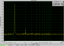
At least the closedloop distortion of the rloaded amp measured quite identical to the values predicted from sims. (Means that sims are quite useful)
Sims predicted 0.0022% for attached measuring.
Mike
At least the closedloop distortion of the rloaded amp measured quite identical to the values predicted from sims. (Means that sims are quite useful)
Sims predicted 0.0022% for attached measuring.
Mike
Attachments
mikeks said:How exactly did you simulate your amp open loop?
Schematic please.
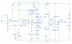
Mikeks, i simply cutted the feedback path, and shorted the feedback node to ground.
With some trying/calcing i set the correct input signal and ran a normal transient analysis.
For the amp without the vas loaded, i had to increase the 22k at feedback node by 20ohms to keep dc-offset below 1v. I did not want the dc-offset to influence the result.
The cascode to the vas is a bit simplified, but doing it correctly does not change much.
The signal sources in the powersupply were inactive.
Mike
Attachments
roender said:Hi Mike
What is the benefit of new added transistors in VAS and current mirror?
Hi Roender,
the current mirror is better balanced and in theory thermally more stable. The added transistors in vas are cascodes and eliminate the 2nd harmonic.
Mike
MikeB said:
... and eliminate the 2nd harmonic.
Mike
But this is a "good" harmonic! Do you want to eliminate that?
MikeB said:
... and eliminate the 2nd harmonic.
Mike
But this is a "good" harmonic! Do you want to eliminate that?
Mikeks,
You wrote:
There are none so blind as those who will not see.....
I could handle your unwillingness to see MikeB's point here, no problem, we all have our blind spots, but to heap derision on a very valid point from a position of lofty arrogance is difficult to take. Why can you not be more tolerant? Your obvious intelligence just makes this even more damning.....
POINTS TO NOTE:
1. The Zout of the VAS collector is a high impedance and thus the voltage output is severely influenced by its load, which of course must be corrected by global feedback.
2. Current shunted into a drone resistor from the VAS will be considerable, and will lower the OLG considerably. BUT this current will dwarf the current required by the driver base at crossover and even at maximum signal excursion, and the combined current draw as a result, particularly about the 'dead zone', will be more even, that is, linear with applied voltage.
3. It is difficult to say that such a shunt resistor will not considerably alter the distortion profile, particularly at the crossover zone.
4. Trying it, and listening, before making such categoric statements, might be in order.
Aside from all this, you are 1 smart fellow, doubtless a lovely chap, have a good day!!
Cheers,
Hugh
You wrote:
On the contrary, it is not merely about ''a point of view'', rather, it is fundamentally about reality on one hand, and fiction on the other.
There are none so blind as those who will not see.....
I could handle your unwillingness to see MikeB's point here, no problem, we all have our blind spots, but to heap derision on a very valid point from a position of lofty arrogance is difficult to take. Why can you not be more tolerant? Your obvious intelligence just makes this even more damning.....
POINTS TO NOTE:
1. The Zout of the VAS collector is a high impedance and thus the voltage output is severely influenced by its load, which of course must be corrected by global feedback.
2. Current shunted into a drone resistor from the VAS will be considerable, and will lower the OLG considerably. BUT this current will dwarf the current required by the driver base at crossover and even at maximum signal excursion, and the combined current draw as a result, particularly about the 'dead zone', will be more even, that is, linear with applied voltage.
3. It is difficult to say that such a shunt resistor will not considerably alter the distortion profile, particularly at the crossover zone.
4. Trying it, and listening, before making such categoric statements, might be in order.
Aside from all this, you are 1 smart fellow, doubtless a lovely chap, have a good day!!
Cheers,
Hugh
Guys,I never know that the VAS of Lizi will become a debating issue😱.At the begining,I just want to share this minimalist amp with you all.
🙂
🙂
Hi, MikeB,
Sometimes ago I experimented exactly in this area, the connection of VAS to the next stage (output stage or predriver).
I don't have enough equipment to measure anything, but here is my conclusion :
1. Base stoppers is needed to connect VAS to the next stage.
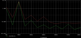
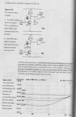
2. Loading the VAS with resistor to ground (fig 4.23.a) has another "more effective" method, that is fig 4.23.b. You can see in the curve below, with this method, the openloop curve is flattened in the lower freqs. The bandwith is still the same, but the corner frequency moves higher, because the lower frequencies is flattened. In the example with R=220k, the corner moves from 800hz to 20khz. Notice that the graph is mirrored.
3. This method is used by Nelson Pass. Put resistor from VAS collector to output node. In this example it is the 2x4k7 resistors.
This method is very elegant and effective (like all NP's tought 😀)
I see the connection between vas and outputstage as the largest source for openloop distortion. Todays output devices have distortion of ~0.05% when fed from a low impedance source. Beeing fed by a ~inf impedance source, the same outputstage gives 1%.
Sometimes ago I experimented exactly in this area, the connection of VAS to the next stage (output stage or predriver).
I don't have enough equipment to measure anything, but here is my conclusion :
1. Base stoppers is needed to connect VAS to the next stage.
2. Loading the VAS with resistor to ground (fig 4.23.a) has another "more effective" method, that is fig 4.23.b. You can see in the curve below, with this method, the openloop curve is flattened in the lower freqs. The bandwith is still the same, but the corner frequency moves higher, because the lower frequencies is flattened. In the example with R=220k, the corner moves from 800hz to 20khz. Notice that the graph is mirrored.
3. This method is used by Nelson Pass. Put resistor from VAS collector to output node. In this example it is the 2x4k7 resistors.
This method is very elegant and effective (like all NP's tought 😀)
Attachments

AKSA said:
POINTS TO NOTE:
1. The Zout of the VAS collector is a high impedance and thus the voltage output is severely influenced by its load, which of course must be corrected by global feedback.
2. Current shunted into a drone resistor from the VAS will be considerable, and will lower the OLG considerably. BUT this current will dwarf the current required by the driver base at crossover and even at maximum signal excursion, and the combined current draw as a result, particularly about the 'dead zone', will be more even, that is, linear with applied voltage.
3. It is difficult to say that such a shunt resistor will not considerably alter the distortion profile, particularly at the crossover zone.
4. Trying it, and listening, before making such categoric statements, might be in order.
Aside from all this, you are 1 smart fellow, doubtless a lovely chap, have a good day!!
Cheers,
Hugh
Whether the second stage's relatively high output impedance at very LF is of significance depends on your output stage topology.
Your explanation looks attractively plausible, but, like much else here, is incorrect, i fear: the performance of an electrical/electronic circuit, of whatever complexion, can never be improved by merely increasing its loading. This is key.
In this regard, i have found MikeB's simulations to be aberrations, irreproducible in practice, and, perhaps, peculiar to his version of SPICE.
- Status
- Not open for further replies.
- Home
- Amplifiers
- Solid State
- latest version of Lizi