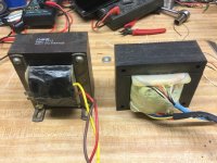
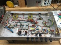
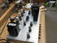
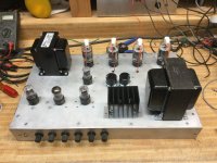
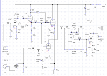
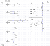
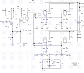
The latest in the series of tube amp projects in progress - a bass amp. My original idea was a big bruiser using 6550’s, but that ended up as a hi-fi monoblock and eventually a pair. Didn’t want to commit that much resources to something I’m likely only to dabble in - I’m no “real” musician but I do build hi-fi PA gear. I wanted something more a match for the intended speaker, and didn’t cost $1000 to build for the “tube bass guitar amp.” Home brew power transformer, $5 output tubes, but decent quality output iron - the only place I spent any real money. Got most of it built now, in the process of getting it up and running. Pretty standard pre amp, but added a sweepable mid. Power section pretty simple and straightforward - but with a couple twists. All octals to make wiring easy. 26DQ5 output tubes with G2 fed from a low voltage tap on the main power supply, and a true LTP phase splitter using the negative rail. When you make your own power transformer from scratch you can just put on all the windings you need to make something work. The original “donor” core was a 500VA EI I picked up for $15 some 20 odd years ago. I still had three left out of a batch. The schematic I ended up with to follow when I get on the other computer with my design software on it.
Attachments
The schematic I ended up with. Tone control values still being tweaked. These were the starting points. I think I have the bugs worked out of the power amp.
Attachments
Last edited:
Just out of couriosity
Are you really having all the primaries of the power supply transformer(s) in series?
It looks rather odd - I would have expected the primaries to be in parallel or given your comment on the schematics: just one primary with several secondaries all sharing the same core.
Otherwise it is very nice to see somebody going in a very different direction as I went with my bass rig design.
Gives food for thought.
Best regards
Martin
It’s all one primary (185 turns of #15) - just loo lazy to make a custom schematic symbol for a multi secondary trafo.
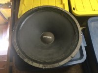
I’ll get to making the cabinets for the head and the speaker after I’m done nursing this broken collarbone. Can’t go wrestling 4x8 sheets of plywood right now. Probably be well into summer before I get around to Duartexiing even after the cab gets built. I tend to do a lot at once when t cones to finishing speakers. What’s going in it is a vintage 18” Pyle driver. Always loved the tone - years ago I ran a pair off an old Fisher tube receiver that doubled as a bass guitar rig.
I’ll get to making the cabinets for the head and the speaker after I’m done nursing this broken collarbone. Can’t go wrestling 4x8 sheets of plywood right now. Probably be well into summer before I get around to Duartexiing even after the cab gets built. I tend to do a lot at once when t cones to finishing speakers. What’s going in it is a vintage 18” Pyle driver. Always loved the tone - years ago I ran a pair off an old Fisher tube receiver that doubled as a bass guitar rig.
Attachments
Got the last of the bugs out of the power section this afternoon. About every third or fourth time powering it up, it would go into a weird latch up mode and put out a highly distorted 60 Hz buzz at about half power. Turns out the phase splitter had an intermittent h-k short. Or at least enough leakage to use up all the tail current and clamp the cathode to zero instead of floating up to 80 volts like it’s supposed to. The hum injected by the heater would excite just one output pair at full drive. New tube (well, a different 1960s vintage one) and it hasn’t done it since. I’ll have to try that tube in a grounded cathode application to see if it’s useable at all, or just chunk it. Still got a little 120 Hz buzz to track down pre-master-volume. Gives me something to do.
Measured power output is 136 watts (33 volts RMS with 8 ohm dummy load) backed off just below clipping Right on target. I’m running the output tube bias at 20 mA per tube, and those old sweeps are pretty steady. I would have expected more drift than I’m seeing, and the match between 4 random ones is pretty good. I do have individual control and can dial them individually - but they stay balanced even at drive. This is good because the really BIG sweep tube amp will be using a toroidal output trafo. Can’t have much imbalance in that or it won’t work.
Measured power output is 136 watts (33 volts RMS with 8 ohm dummy load) backed off just below clipping Right on target. I’m running the output tube bias at 20 mA per tube, and those old sweeps are pretty steady. I would have expected more drift than I’m seeing, and the match between 4 random ones is pretty good. I do have individual control and can dial them individually - but they stay balanced even at drive. This is good because the really BIG sweep tube amp will be using a toroidal output trafo. Can’t have much imbalance in that or it won’t work.
Do you get much variation in 26DQ5 idle grid current across each 100k , and screen current across each 110R stopper?
I guess you could fuse the 220V secondary, although that would also require a steering diode across the 330uF if there was a HT short type fault.
I guess you could fuse the 220V secondary, although that would also require a steering diode across the 330uF if there was a HT short type fault.
Usually I just monitor the 4 cathode currents. I have a port on the back for that, an a connector to monitor up to 6 at a time. If the currents all drive up the same I don’t see much cause to look further. When that weird fault occurred due to the bad driver tube, the two tubes on one side drove up to 147 mA and the other two maybe 5 mA. The high side was getting about 60V peak to peak 60 Hz square-ish wave drive and the other was getting a volt or two. The overall current draw was within safety limits of the power supply and the OPT, but the DC offset in the OPT would be concerning. It’s not meant for SE use. Tubes didn’t stay on long enough to red plate. It didn’t seem to hurt anything, but might have been hell on the speaker. 240 watt dummy load didn’t care.
I think if I fused anything (other than the main, which has a 7 amp quick blow now) it would be the 120V *screen* winding. That would drop the HT by a third, and cut the output tubes off with Vg2 at zero. If I fused just the 220 volt, the screen would act as an *anode* since the heaters are still on. I have the HT trafo separately fused and powered in my 200 watt monoblocks, but the heaters for the 6550’s run off the same trafo. Lose the HT and emissions at the same time so the screens stay safe eve with Vg2 still applied. The screen regulator on that amp folds back and drops out of regulation at 300 mA (100 mA per tube) to keep the peaks in check.
I think if I fused anything (other than the main, which has a 7 amp quick blow now) it would be the 120V *screen* winding. That would drop the HT by a third, and cut the output tubes off with Vg2 at zero. If I fused just the 220 volt, the screen would act as an *anode* since the heaters are still on. I have the HT trafo separately fused and powered in my 200 watt monoblocks, but the heaters for the 6550’s run off the same trafo. Lose the HT and emissions at the same time so the screens stay safe eve with Vg2 still applied. The screen regulator on that amp folds back and drops out of regulation at 300 mA (100 mA per tube) to keep the peaks in check.
Doh, sorry I should have said fuse the 110V winding.
Measuring the input grid and screen grid currents was mainly about your comment of using random 26DQ5 - as an initial check that random valves are all showing nominal grid performance. Yeh I also always aim to provide a monitoring connector to provide periodic peace of mind that the basic operating levels are ok.
Measuring the input grid and screen grid currents was mainly about your comment of using random 26DQ5 - as an initial check that random valves are all showing nominal grid performance. Yeh I also always aim to provide a monitoring connector to provide periodic peace of mind that the basic operating levels are ok.
- Home
- Live Sound
- Instruments and Amps
- Latest project - a bass amp with sweep tiubes