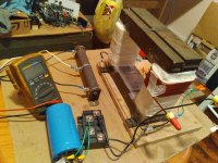
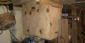
Hello , I am currently building transformer for powering car amplifiers in home . The original plan was to use the transformer unregulated , but the voltage drop under even a small load is unacceptable . The transformer is good for 1750 va . I am hoping to succeed in getting maybe 130 amps at 14 volts with some type of constant voltage / constant current regulation scheme . I thought about multiple off-shelf buck converters in parallel , but I'm finding that unless they are designed for master-slave operation , you cannot accomplish this . The primary is done and the secondary is not because I don't know which voltage to wind for considering the lack of knowledge concerning the best ( and cheapest ) way to realize this . Thanks ahead of time for any good advice .
Attachments
Please draw current power supply schematic and transformer specs, also intended load.
99.9% of amplifiers out there use unregulated power supplies, no big deal, you should be able to.
State unloded, lightly loaded and full loaded voltages.
99.9% of amplifiers out there use unregulated power supplies, no big deal, you should be able to.
State unloded, lightly loaded and full loaded voltages.
No, unregulated supply is not possible at that voltage/current. If you want 14 volts at that kind of current it will be 20 unloaded - which is too high for safe operation of a CAR amp. To keep a 10% regulation figure you’d need a 5 kVA trafo, maybe even more. A buck converter is the only practical solution. You WANT a steady 14 volts to make best use of the amp(s). For better efficiency, you don’t need to start out that low in raw voltage - maybe wind the trafo up for 20 volts, giving 28 no load and 20-22 full load. I doubt you will find a suitable off the shelf converter, but a buck converter is relatively “easy” as switch mode devices go. Far easier at this power level than an off-line SMPS (I wouldn’t recommend trying this for your first rodeo - you will get “bucked” off and end up in the hospital).
Necessary circuit protection would consist of a fuse ahead of the converter and an OVP crowbar set at about 16-17 volts (Big *** SCR) and a 15 amp primary fuse. If you blow a hexfet by shorting the output buy another. The AMPS will have built in current limiting. You’ll probably need TWO IRFP2907’s or similar with an appropriate high side driver chip, and the same amperage worth of 35 ns diode (60 amp is the largest common one). TL494 or SG3525 (whatever you can get) for PWM regulation. You’ll have to DIY an output inductor - scour the planet for cores like these. Use multiple strands of #15 or so wire (so you CAN wind it) and parallel inductors of you need to. Don’t try to push the frequency up to anything stupid - 40-50 kHz is appropriate. 10 or 20 uH is “enough” inductance - discontinuous operation is ok here, just need to keep di/dt down in the low amps-per-microsecond range and don’t let the core saturate. 10 mu powdered or 60 mu permalloy - no higher. Some newbies get the brilliant idea of using 2000 mu ferrite to reduce size and that doesn’t work out too well.
Necessary circuit protection would consist of a fuse ahead of the converter and an OVP crowbar set at about 16-17 volts (Big *** SCR) and a 15 amp primary fuse. If you blow a hexfet by shorting the output buy another. The AMPS will have built in current limiting. You’ll probably need TWO IRFP2907’s or similar with an appropriate high side driver chip, and the same amperage worth of 35 ns diode (60 amp is the largest common one). TL494 or SG3525 (whatever you can get) for PWM regulation. You’ll have to DIY an output inductor - scour the planet for cores like these. Use multiple strands of #15 or so wire (so you CAN wind it) and parallel inductors of you need to. Don’t try to push the frequency up to anything stupid - 40-50 kHz is appropriate. 10 or 20 uH is “enough” inductance - discontinuous operation is ok here, just need to keep di/dt down in the low amps-per-microsecond range and don’t let the core saturate. 10 mu powdered or 60 mu permalloy - no higher. Some newbies get the brilliant idea of using 2000 mu ferrite to reduce size and that doesn’t work out too well.
Attachments
Hello , I am currently building transformer for powering car amplifiers in home .... 1750 va .... maybe 130 amps at 14 volts ....constant voltage / constant current regulation scheme ....I thought about multiple off-shelf buck converters in parallel ... The primary is done and the secondary is not because I don't know which voltage to wind..
Dear Nealzy,
The best topology for 100+ amperes is the multi-phase (interleaved) buck converter. For 130A, you will need 5-6 phases with 20-25A in each phase. With some margin for load regulation, the unregulated side must be about ~20V to get approximately 75% to 80% duty cycle at the output.
There are some caveats with high current designs for example, your PCB could heat up, so be careful with placement, routing and distances. Another issue you're likely to face is regarding the current-sharing between the phases, and then you'll need protection.
But before all that, do you really need so much power?
All the best.
Yeah the unregulated unloaded rectified voltage was 14.4 volts and fell to 12.4 volts with a 103 watt load .... This is the first time I have tried to build a regulated supply , complete newbie to this type of thing . Was looking at some things on the net about people using the lm317 and other components ( for the heavy lifting ) . I think building a buck converter would be more efficient though , so I like the suggestion .
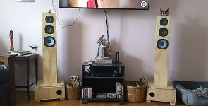
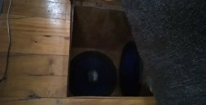
I suppose I don't need all the power ( all the time ) but I have two large class d car amps and two 12s in a sub box hanging from the floor joist under the couch in the theater ( living ) room .... sometimes it gets loud . I was driving one 12 with an iraud 350 , and the other with a smps powered mtx 600 watt car amp . The iraud shot itself and now I'm back with the years old original plan of building a power supply . The transformer core and primary magnet wire were already on hand , so that much is assembled... This buck converter is my next plan ( with a lot of guidance of course ) . I could just buy another smps and keep that up every 8 months or so , as the system stays on most of the time . I want to build something for myself is the largest reason for this project . 5 or six phases.... , sounds kind complicated on the face of it . Would you please elaborate or maybe help with a tutorial link . ThanksDear Nealzy,
The best topology for 100+ amperes is the multi-phase (interleaved) buck converter. For 130A, you will need 5-6 phases with 20-25A in each phase. With some margin for load regulation, the unregulated side must be about ~20V to get approximately 75% to 80% duty cycle at the output.
There are some caveats with high current designs for example, your PCB could heat up, so be careful with placement, routing and distances. Another issue you're likely to face is regarding the current-sharing between the phases, and then you'll need protection.
But before all that, do you really need so much power?
All the best.
Firstly, it is highly likely that you're overestimating your power requirements. So, could you state the size (volume) of your listening space and the sensitivity (dB/W/m) of your speakers ?
https://www.ti.com/lit/an/slva882b/slva882b.pdf
https://www.ti.com/lit/an/slva882b/slva882b.pdf
No, unregulated supply is not possible at that voltage/current. If you want 14 volts at that kind of current it will be 20 unloaded - which is too high for safe operation of a CAR amp. To keep a 10% regulation figure you’d need a 5 kVA trafo, maybe even more. A buck converter is the only practical solution. You WANT a steady 14 volts to make best use of the amp(s). For better efficiency, you don’t need to start out that low in raw voltage - maybe wind the trafo up for 20 volts, giving 28 no load and 20-22 full load. I doubt you will find a suitable off the shelf converter, but a buck converter is relatively “easy” as switch mode devices go. Far easier at this power level than an off-line SMPS (I wouldn’t recommend trying this for your first rodeo - you will get “bucked” off and end up in the hospital).
Necessary circuit protection would consist of a fuse ahead of the converter and an OVP crowbar set at about 16-17 volts (Big *** SCR) and a 15 amp primary fuse. If you blow a hexfet by shorting the output buy another. The AMPS will have built in current limiting. You’ll probably need TWO IRFP2907’s or similar with an appropriate high side driver chip, and the same amperage worth of 35 ns diode (60 amp is the largest common one). TL494 or SG3525 (whatever you can get) for PWM regulation. You’ll have to DIY an output inductor - scour the planet for cores like these. Use multiple strands of #15 or so wire (so you CAN wind it) and parallel inductors of you need to. Don’t try to push the frequency up to anything stupid - 40-50 kHz is appropriate. 10 or 20 uH is “enough” inductance - discontinuous operation is ok here, just need to keep di/dt down in the low amps-per-microsecond range and don’t let the core saturate. 10 mu powdered or 60 mu permalloy - no higher. Some newbies get the brilliant idea of using 2000 mu ferrite to reduce size and that doesn’t work out too well.
Firstly, it is highly likely that you're overestimating your power requirements. So, could you state the size (volume) of your listening space and the sensitivity (dB/W/m) of your speakers ?
https://www.ti.com/lit/an/slva882b/slva882b.pdf
I'd have to say you are probably correct about the overestimation of current... , but the possibility of powering more than one car amp is the plan as I have three car amps not being used at the moment . The room is 11' x 18' , spl ratings , have no clue . Speakers are from various manufacturers , sony , kenwood , pioneer , plye , power acoustik , bose ...
Attachments
-
 USER_SCOPED_TEMP_DATA_MSGR_PHOTO_FOR_UPLOAD_1648993566943_6916380313804454586.jpeg133.6 KB · Views: 77
 -
 USER_SCOPED_TEMP_DATA_MSGR_PHOTO_FOR_UPLOAD_1648993657845_6916380695075412786.jpeg104.1 KB · Views: 76
 -
 USER_SCOPED_TEMP_DATA_MSGR_PHOTO_FOR_UPLOAD_1648993975514_6916382027477465680.jpeg151.2 KB · Views: 75
 -
 USER_SCOPED_TEMP_DATA_MSGR_PHOTO_FOR_UPLOAD_1648993764574_6916381142730357355.jpeg182.9 KB · Views: 76
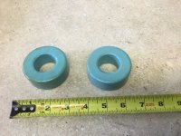
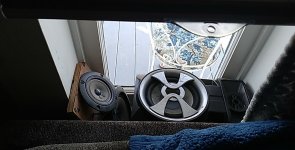
What type material is the toroid shown .... , looks like 2.5 inch o.d. , what are true measurements or a part # maybe .No, unregulated supply is not possible at that voltage/current. If you want 14 volts at that kind of current it will be 20 unloaded - which is too high for safe operation of a CAR amp. To keep a 10% regulation figure you’d need a 5 kVA trafo, maybe even more. A buck converter is the only practical solution. You WANT a steady 14 volts to make best use of the amp(s). For better efficiency, you don’t need to start out that low in raw voltage - maybe wind the trafo up for 20 volts, giving 28 no load and 20-22 full load. I doubt you will find a suitable off the shelf converter, but a buck converter is relatively “easy” as switch mode devices go. Far easier at this power level than an off-line SMPS (I wouldn’t recommend trying this for your first rodeo - you will get “bucked” off and end up in the hospital).
Necessary circuit protection would consist of a fuse ahead of the converter and an OVP crowbar set at about 16-17 volts (Big *** SCR) and a 15 amp primary fuse. If you blow a hexfet by shorting the output buy another. The AMPS will have built in current limiting. You’ll probably need TWO IRFP2907’s or similar with an appropriate high side driver chip, and the same amperage worth of 35 ns diode (60 amp is the largest common one). TL494 or SG3525 (whatever you can get) for PWM regulation. You’ll have to DIY an output inductor - scour the planet for cores like these. Use multiple strands of #15 or so wire (so you CAN wind it) and parallel inductors of you need to. Don’t try to push the frequency up to anything stupid - 40-50 kHz is appropriate. 10 or 20 uH is “enough” inductance - discontinuous operation is ok here, just need to keep di/dt down in the low amps-per-microsecond range and don’t let the core saturate. 10 mu powdered or 60 mu permalloy - no higher. Some newbies get the brilliant idea of using 2000 mu ferrite to reduce size and that doesn’t work out too well.
Thanks for the info link ....Firstly, it is highly likely that you're overestimating your power requirements. So, could you state the size (volume) of your listening space and the sensitivity (dB/W/m) of your speakers ?
https://www.ti.com/lit/an/slva882b/slva882b.pdf
The average current requirement is probably about 4 or 5 amps, 20 when playing loud. But that kind of car amp will draw 100+ amps repetitively on each bass beat when driven to clip. It makes the headlights dim down to the beat. A power supply must be able to support those surges without anything bad happening. Going into current limit or dropping down to 8 volts qualifies as “bad” even if it doesn’t explode (Because the amp power will be severely limited or it may shut down).Firstly, it is highly likely that you're overestimating your power requirements. So, could you state the size (volume) of your listening space and the sensitivity (dB/W/m) of your speakers ?
https://www.ti.com/lit/an/slva882b/slva882b.pdf
If you don’t need crazy SPL, get a smaller amp that doesn’t need crazy amperage. A 200 watt amp may do fine, and a 20 or 25 amp supply is easy.
What are you using for rectification? How large is the capacitor? It sound like either it's sagging because there isn't enough capacity, or the rectifiers are dropping significant voltage under loading...Yeah the unregulated unloaded rectified voltage was 14.4 volts and fell to 12.4 volts with a 103 watt load .... This is the first time I have tried to build a regulated supply , complete newbie to this type of thing . Was looking at some things on the net about people using the lm317 and other components ( for the heavy lifting ) . I think building a buck converter would be more efficient though , so I like the suggestion .
You say you have 14.4V unloaded, I calculate the transformer to be a 10VAC coil, right?
They are 2.5”, 60 mu permalloy. Picked a dozen up at Skycraft many years ago, still got a couple left. They would be stupid expensive on the regular market. I used a couple for big off-line buck converters (non audio rated, but made lots of hydrogen with one and powered a big laser with the other) and some for class D output filters.What type material is the toroid shown .... , looks like 2.5 inch o.d. , what are true measurements or a part # maybe .
That is correct . Cap is 16000uf 60v and rectifier bridge is rated for 200 ampsWhat are you using for rectification? How large is the capacitor? It sound like either it's sagging because there isn't enough capacity, or the rectifiers are dropping significant voltage under loading...
You say you have 14.4V unloaded, I calculate the transformer to be a 10VAC coil, right?
That's pretty small dude. Add a couple of zeros? 🙂 That and the forward voltage drop of the diodes will cause this kind of drop out...
Of course you'll probably need some inrush limiting to use a 2 farad cap 🙂

https://www.amazon.com/BOSS-Audio-C...e.com/reviews/29562/best-car-audio-capacitors
Of course you'll probably need some inrush limiting to use a 2 farad cap 🙂
https://www.amazon.com/BOSS-Audio-C...e.com/reviews/29562/best-car-audio-capacitors

20,000 uF is “the right value”, but that would be referred to the amp’s actual internal supply voltage. If it’s really running on +/-70V internally, that’s a 140 volt supply. If you're starting at 14 volts to get that, you multiply by 10. Which puts the cap requirement at 200,000 uF. You’ll still only get 70-75% regulation at full the VA capacity of the transformer. Ripple goes down but the peak currents increase in magnitude and get narrower in conduction angle as the cap is increased. A 2 farad would be overkill, and probably szhekx the rectifier.
I have yet to hook any amp to this transformer... , I wound enough secondary winding to simply find out what kind of voltage drop I might be looking at unregulated.... 100 watt load and a 2 volt drop is what I found . I don't see the cap size is a problem at that current... , or am I wrong ? I've decided that a buck converter is beyond my grasp and the car amps aren't a option anymore . Irs 2092 based amps are cheap and plentiful and the appropriate sized magnet wire is also . Class d kinda was the root of this transformer build years ago .I'll just revert back to the original plan as I was banking on the assumption that a class d amp wasn't to picky about regulation to start off with .20,000 uF is “the right value”, but that would be referred to the amp’s actual internal supply voltage. If it’s really running on +/-70V internally, that’s a 140 volt supply. If you're starting at 14 volts to get that, you multiply by 10. Which puts the cap requirement at 200,000 uF. You’ll still only get 70-75% regulation at full the VA capacity of the transformer. Ripple goes down but the peak currents increase in magnitude and get narrower in conduction angle as the cap is increased. A 2 farad would be overkill, and probably szhekx the rectifier.
For a 100 watt load, you appear the be following the other commonly used rule of thumb for non-audio applications - 2000 uF per ampere. You could run a car amp off that - just not a 1000 watter at full volume. It would be typical of the average draw of say a 100 or 150 watt amp (a practical size).
If you we’re considering a class D amp and could just build one, it would be better to just wind up the voltage you need to run it, rather than step it down and regulate to 14 volts, then use a DC-DC converter to generate what you would have gotten in the first place, just to run a class D car amp. The reason to use a car amp is if that’s what you had and you were going to use it. If there is another choice, it’s probably better.
If you we’re considering a class D amp and could just build one, it would be better to just wind up the voltage you need to run it, rather than step it down and regulate to 14 volts, then use a DC-DC converter to generate what you would have gotten in the first place, just to run a class D car amp. The reason to use a car amp is if that’s what you had and you were going to use it. If there is another choice, it’s probably better.
- Home
- Amplifiers
- Power Supplies
- Large transformer build ...., simple voltage regulation advice needed