First, measure in none of the transistors is failed shortcircuited or bad soldered to the PCB. The circuits appears to be right.
Yes, although some previous stage bad biased (cut off or saturated), or shortcircuited / opened can cause a chain of bad things.Is it more likely to be the output transistors? I've already had to change some faulty ones.
Add an RF filter to the input.
Temporarily disconnect R5.
Change R24 to a lower value.
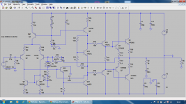
Add 4 diodes. One to each of C7, C8, {Q5+R20}, {Q15+R19}.
Insert a resistor Q11 collector to GND.
None of these changes will "cure" your offset.
Temporarily disconnect R5.
Change R24 to a lower value.
Add 4 diodes. One to each of C7, C8, {Q5+R20}, {Q15+R19}.
Insert a resistor Q11 collector to GND.
None of these changes will "cure" your offset.
I just realised I had been stupidly only putting +-30V across the supply rails, as that's what I used for a previous amplifier. Would that be the likely cause?
I built my amp and tested it to find it had an amazingly high -18V dc offset. Any suggestions why this occurs?
70 Volt output transistors with a 100 Volt power supply? Looking for trouble. The drivers are hanging on the edge too.
G²
70 Volt output transistors with a 100 Volt power supply? Looking for trouble. The drivers are hanging on the edge too.
G²
Surely only 50V max will go through each output transistor though as the npn's are only on for the +ve half of the output and pnp's for the negative. I've seen amps with the exact same output setup work fine.
No.
The worst case voltage across an output transistor is rail to rail + ~0.7Vdc, when protection diodes have been fitted across the output devices.
If the diodes are omitted, the worst case voltage can be higher than rail to rail.
The worst case voltage across an output transistor is rail to rail + ~0.7Vdc, when protection diodes have been fitted across the output devices.
If the diodes are omitted, the worst case voltage can be higher than rail to rail.
Oh, ok. Well I'll see how long they last, I have got all the components from my university so far so not a worry if the fail under testing. Should I go for a transistor with a Vce rating of at least 100V then?
Thanks
Thanks
Oh, ok. Well I'll see how long they last, I have got all the components from my university so far so not a worry if the fail under testing. Should I go for a transistor with a Vce rating of at least 100V then?
Thanks
I would use one of >150V, assuming a 50% security margin.
Oh, ok. Well I'll see how long they last, I have got all the components from my university so far so not a worry if the fail under testing.
Yes, it is a worry - especially if a fire extinguisher is not handy. And if you're not worried about pieces of plastic power transistor cases flying around the room. The first time you get hit with a flaming piece of a TO-218 will teach you things they don't in the classroom.
Use a current limited supply if you have it, and keep the voltage dialed down until you get it working right.
Surely only 50V max will go through each output transistor though as the npn's are only on for the +ve half of the output and pnp's for the negative. I've seen amps with the exact same output setup work fine.
You are a rookie, I knew you would say that and it's wrong. Yes, when there is no signal there is only 50 Volts on your transistors. Drive it to clipping with or without a load and the full supply Voltage of 100 Volts will be across each power transistor. The positive transistor will get 100 on negative peaks and the negative transistor gets 100 on positive peaks. The transistor are connected together so any signal shows up on both. If you don't believe me put a scope on it.
The input differentials will not get the full supply but the VAS, drivers and outputs will.
G²
You are a rookie, I knew you would say that and it's wrong. Yes, when there is no signal there is only 50 Volts on your transistors. Drive it to clipping with or without a load and the full supply Voltage of 100 Volts will be across each power transistor. The positive transistor will get 100 on negative peaks and the negative transistor gets 100 on positive peaks. The transistor are connected together so any signal shows up on both. If you don't believe me put a scope on it.
The input differentials will not get the full supply but the VAS, drivers and outputs will.
Well it's not that I don't believe you, I just didn't know, but now I do. I appreciate your help but I don't appreciate being patronised, just because I don't have as much experience or knowledge as you do.
- Status
- Not open for further replies.
- Home
- Amplifiers
- Solid State
- Large DC offset