Long story in short.
Amp produces output and works just fine under 13volts of input B+.
Once I feed it over 13volts it goes into protect and stays there till I drop the input voltage under 13volts from my laboratory power supply.
I've removed the rectifiers to isolate the ps section from the amplifier one - power supply section works great, no protection, nothing even at 15volts, so it's not the PS.
So far I've changed the two LM293, the two optocouplers tlp521-2, the JRC 1300D OP AMP, and checked every other OP amp and their supply voltages on the main board - all fine.
The two voltage regulators 7915 and 7815 are giving their respective +-15volts.
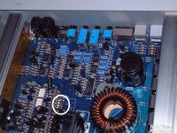
The only thing I don't know is the chip on the Driver Board Module in DIP8 form factor in the picture.
I've already pulled out the Driver Board Module and checked every transistor and diode with a Multimeter in diode mode to confirm there is no shorted ones. I know these can get hot quite a lot. All reads fine.
Any ideas ?! 😕
Amp produces output and works just fine under 13volts of input B+.
Once I feed it over 13volts it goes into protect and stays there till I drop the input voltage under 13volts from my laboratory power supply.
I've removed the rectifiers to isolate the ps section from the amplifier one - power supply section works great, no protection, nothing even at 15volts, so it's not the PS.
So far I've changed the two LM293, the two optocouplers tlp521-2, the JRC 1300D OP AMP, and checked every other OP amp and their supply voltages on the main board - all fine.
The two voltage regulators 7915 and 7815 are giving their respective +-15volts.
The only thing I don't know is the chip on the Driver Board Module in DIP8 form factor in the picture.
I've already pulled out the Driver Board Module and checked every transistor and diode with a Multimeter in diode mode to confirm there is no shorted ones. I know these can get hot quite a lot. All reads fine.
Any ideas ?! 😕
Attachments
Post #3 has a diagram.
Generic Asian Clone driver board RE and Clone
That op-amp is in the feedback circuit for the class D output section.
Generic Asian Clone driver board RE and Clone
That op-amp is in the feedback circuit for the class D output section.
I think the problem is somewhere on the main board, not in the driver module card. Amp goes into protect over 13volts even if the driver board is out (mosfets were still in place).
Thanks for the link Perry !
Thanks for the link Perry !
Last edited:
This diagram isn't perfect but if you don't have anything better, it's better than nothing.
http://www.bcae1.com/temp/KX1-5500D_sch.pdf
http://www.bcae1.com/temp/KX1-5500D_sch.pdf
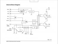
So I've measured every pin on the KA3525A and the only thing I noticed which was odd was pin 8 - which is for soft start function.
If input voltage is lower than 13volts of B+, pin 8 stays at around 4.7vrms. Once I up the voltage over 13v, it goes to 0v, like it's grounding but nothing heats up. Then if I lower the input voltage again but under 13volts, pin 8 slowly rises again to 4.7vrms and amp kicks in operation mode.
What I've noticed looking at the diagram of KA3525A that pins 1, 2, 9, 10 even that they are internally connected with pin 8, they does NOT change their values in terms of Vrms. They stay the same no matter of the b+ input voltage.
Everything else looks ok. VCC, GND, Ct, Vref, Outputs A & B, looks great...but once the voltage passes over 13v+, no more output at pins 11 and 14
Attachments
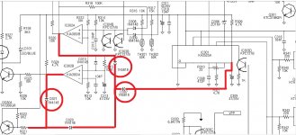
A little bit of investigating, pin 8 the soft start, gets its voltage from the output of one of the LM293P. Going over 13volts of b+, cuts out the voltage on pin 1 "1out" of the LM293P...
The only values that are in direct correlation with the b+ of LM293P are the IN+ inputs and the outputs. The IN- stays the same all time ~ 2,7vrms.
The supply voltage of the LM293P stays also the same all the ~ 5.07vrms.
But how does pin8 for the soft start even gets its voltage when there are diodes in the way in reverse orientation ?!
I'm not really good at reading schematics...🙁
And yeah, I know my paint skills are incredible 😀😀😀
Attachments
Last edited:
Okay, that's what I thought too.
Found two 1n5819 diodes reading ~ 210 in diode mode one way, and nothing in the other...i'm going to get a new ones, but i don't think these ones are the bad guys....
And the schematics I posted earlier does not match exactly with the board in front of me...mine seems to be another revision. There are some differences...
If you like Paint (or more likely, use it because you have it), try paint.net. You can work in layers so you can redo mistakes without starting over.
Is the regulator for the IC working? It should limit the voltage to about 12.5v. How much voltage is getting to the IC?
These ICs (3525) sometimes fail in strange ways. If you never find the reason it's shutting down, you should try replacing it.
Is the regulator for the IC working? It should limit the voltage to about 12.5v. How much voltage is getting to the IC?
These ICs (3525) sometimes fail in strange ways. If you never find the reason it's shutting down, you should try replacing it.
Voltage to the IC is limited ~ 12.16vrms, doesn't go more than that even with 15volts of b+ input.
Fitted the new diodes - same stuff. Nothing changed. I bought the 3525 IC, but what is still confusing me - when the rectifiers are out of the board - NO PROTECT, so its not the power supply damaged but the amplifier section.
Before changing the 3525, i will pull out all of the power mosfets in the amplifier section and see if it's going in protect without them...I'm not really looking forward to desolder and resolder again a load of mosfets....
Is there any chance that an amplifier section mosfet can work with a lower rail voltage but to fail with higher one without destroying anything but making the amp to go in protect mode ?!
Okay some more funky stuff is going on. All of the tests are done at 12volts b+.
If I probe pin 4 on the KA3525A with the oscilloscope the transformers are giving a terrible buzzing sound and my power supply goes into protect due to overcurrent. No matter if I use primary DC ground or the secondary (RCA shields) for the oscilloscope ground.
If I probe the hdrv or vcc on the driver class D module - amp goes into protect. Leaving the probe there, on the pin, during the restart process of the amp, brings back the amp live, but once I remove the probe it goes again in protect and i have to wait again for the amp to restart itself. I feel like the oscilloscope is grounding something or closing some circuit...never had this before...
Don't pull all of the FETs.
With a strong test tone signal driven into the amp, when you had the rectifiers out, did you confirm that the high and low-side FETs had good drive signal? Don't pull the rectifiers to check this if you haven't do so already.
Pins 1 and 2 for the two optocouplers are the input to the protection circuit. Bridge them together (you can do so with a meter probe). Does bridging either allow the amp to remain on?
When it goes into protect, does pin 3 drop below the 2.7v on pin 2 lf the 393?
LM 293/393 - pin 3 drops to 0v when amp goes into protect. In working stage it stays at 5vrms.
"Pins 1 and 2 for the two optocouplers are the input to the protection circuit. Bridge them together (you can do so with a meter probe). Does bridging either allow the amp to remain on?"
Pins 1 and 2 - at the optocouples (there are 2 of them) or pins 1 and 2 at the KA3525A ?!
"Pins 1 and 2 for the two optocouplers are the input to the protection circuit. Bridge them together (you can do so with a meter probe). Does bridging either allow the amp to remain on?"
Pins 1 and 2 - at the optocouples (there are 2 of them) or pins 1 and 2 at the KA3525A ?!
For both optocouplers, pins 1 and 2 are the input from various parts of the protection circuit. Bridging them prevents the protection circuit from shutting down the amp.
You're going to bridge one at a time to try to determine what part of the protection circuit is shutting down the amp.
Thank You so much Perry ! 
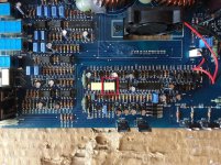
Bridging one of the optocouplers actually makes the amp go out of protect and stays operational with a higher input voltage b+.
The one in the picture in red...so now I have to trace what's wrong with the protection circuit.
Bridging one of the optocouplers actually makes the amp go out of protect and stays operational with a higher input voltage b+.
The one in the picture in red...so now I have to trace what's wrong with the protection circuit.
Attachments
- Status
- Not open for further replies.
- Home
- General Interest
- Car Audio
- Lanzar Opti 2000d goes in protect over 13volts