Also you could remove the main cap and leave the bypass for test only and see what happens. If no DC then it's the cap.
I still have 2 spare caps of each, so rather than swaping the caps L-R vice versa, better to isntall the new one.
No that's not better, because if the fault remains you still know nothing.
If you swap caps you immediately know whether its the caps or something else.
jan
Hi Frank,
I did swap the bypass caps at after the second replacemen of the right channel caps. Problem stayed.
Agree, need even the stragest try to find and solve.
I did swap the bypass caps at after the second replacemen of the right channel caps. Problem stayed.
Agree, need even the stragest try to find and solve.
Hi,
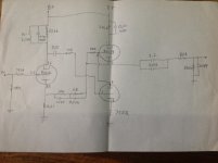
Unfortunately there's a ton of errors in the drawing plus a number of mysterious components.
Assuming a B+ reading of roughly 250VDC where it says B+ then one components that immediately jumps out is the 250VDC decoupling cap in // with the 47mircoF electrolytic to the left top of the drawing. That voltage rating does not make any sense.
Then there are the components in the feedback loop and the way it is attached to the output. Can't believe that's correct either but I assume its just another error in the drawing.
No grid leak resistor on the grid of the bottom triode of the SRRP either. No bias resistor between the two triodes either, etc., etc.
I'll try to correct the drawings you sent me as much as I can and return them to you but other than the cap rating mentioned above and imagining a circuit as I think it should/could be then I don't see any other obvious causes of the DC leakage on the output.
Sorry if I sound a bit harsh but that's just from disappointment, 😉
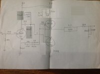
Hi Frank,
Really sorry for the confusion, and many thanks for taking effort to correct the drawing. I will also take this to my friend to ensure we will draw correct scheme then.
Really sorry for the confusion, and many thanks for taking effort to correct the drawing. I will also take this to my friend to ensure we will draw correct scheme then.
lamm ll2.1
HOLA ESTUVE SIGUIENDO EL POST Y ME ATRAPO,PUDIERON TOMAR BIEN EL DIBUJO DEL CIRCUITO HACI DE ESTA MANERA PODER AYUDAR Y SERIA BUENO TAMBIEN EL DE LA FUENTE DE ALIMENTACION PARA VER LAS TENSIONE TAMBIEN Y PODER COLAABORAR. A SUS ORDENES.DANIEL
HOLA ESTUVE SIGUIENDO EL POST Y ME ATRAPO,PUDIERON TOMAR BIEN EL DIBUJO DEL CIRCUITO HACI DE ESTA MANERA PODER AYUDAR Y SERIA BUENO TAMBIEN EL DE LA FUENTE DE ALIMENTACION PARA VER LAS TENSIONE TAMBIEN Y PODER COLAABORAR. A SUS ORDENES.DANIEL
Hello I was following the post and I caught myself, well could take the circuit drawing haci thus would be good to help and also the power supply to see also stress and power colaaborar. Your ordenes.Daniel
English please.
And take your caps locks key off. All caps is considered rude
dave


- Status
- Not open for further replies.
- Home
- Amplifiers
- Tubes / Valves
- Lamm LL2.1 DC Offset problem