You might want to consider starting another thread on the theme of "implementing LADSPA plugins using ALSA and the BBB". That way your particular struggles, most of which are not related to my plugins, can be hashed out there, on topic.
Done! 😉 Here is the link.
Keep up the good work!
Great! It's already quite a resource. You have definitely invested a lot of time on the BBB trying to get the ALSA stuff running smoothly.
I will definitely keep an eye on what you report.
I have been listening to streaming audio using the ecasound/LADSPA crossover and sending audio to the amplifiers via the two USB devices for the last couple of hours. I haven't noticed anything like out of sync audio or other problems. I will continue to test this setup...
I'm following up on the above post: after many hours of testing I haven't detected any difference in the timing between the outputs of the two USB DACs on my Pi 2 system.
This is great news, because to me this represents a pretty good quality 4-channel software-based DSP crossover solution that can be had for about $60 while also serving as a streaming audio client.
Which usb cards do you use?
Very cheap ones that use the PCM2704 chip. Example:
Ele EL-D01
As little as $10-15ea on Ebay including shipping.
Don't believe the "on faith" distortion specs. They are quoting the IC datasheet when the IC is powered by a separate, noiseless supply. Most use the USB bus for power. I measured the distortion at about 0.02% but it's independent of frequency. Noise seems low, but I didn't measure it specifically.
These are perfect for the Pi, and are plug and play under Raspbian.
These are adaptive mode cards, clocked by the usb controller. Since they all are hooked to the same controller, they share a single master clock and run synchronously.
Yet more fun with LADSPA plugins and ecasound on the Raspberry Pi 2
..or how to switch on your amplifier automatically.
Now that I have obtained good quality multichannel audio using two USB stereo DACs with the Raspberry Pi I have been thinking of what other ways that the Pi could be useful. It is commonly known that the GPIO pins can be used to interface with external devices, or can serve as an I2S or I2C bus. I thought I would investigate another way to send signals to external devices: the built-in audio/video jack.
Since I want to embed a Pi in each loudspeaker, working as a DSP crossover, the Pi will likely always be powered up and waiting for an audio signal via my WiFi network. But I don't want the amplifiers constantly powered up. Could I somehow use the A/V jack to send a signal to a relay or other external circuitry to turn the amplifer(s) on only when there is an audio signal present, and turn them off again when no signal has been detected for some period of time? It was time for some thinking and coding...
Fast forward a couple of days, and... I've indeed managed to invent a way to do this using (yet another) LADSPA plugin running under ecasound. Instead of processing the audio in some way (e.g. applying a filter) the LADSPA plugin generates a full-scale square wave at a user-defined frequency. The plugin monitors the input audio stream and identifies the peak signal. Then it compares the peak against a used-defined threshold, e.g. -60dB. If no peak exceeds this threshold a timer is started. As long as the peak remains below the threshold the timer continues to count up. When a user-defined delay has been exceeded the plugin output is muted, e.g. set to all zeros. Subsequently, if the peak signal exceeds the threshold the counter is begun again and as long as the peak continues to exceed the threshold the counter is incremented until another user-specified time is exceeded and the square-wave output signal is again produced by the plugin. This output is an on-delay/off-delay signal.
Ecasound allows the audio stream to be "branched". One branch is used as input to the normal DSP crossover filtering. Another branch can be combined into a mono signal and fed into the on/off delay plugin, processed, and then directed to one channel of the A/V jack of the Raspberry Pi. There are two audio channels available there, so two separate on/off delay plugins can be implemented to give two independent on-delay and off-delay times, both triggered by the same mixed-to-mono audio input stream.
What can you do with the output signal from this plugin? Well, the AV jack output isn't all that high in voltage - I haven't measured it by I believe the maximum Vp-p is about 1-1.2 volts and the current drive capability is likely limited. Some external circuitry will be needed before it can do anything useful. Once I had the plugin working successfully, I designed a simple circuit that uses an active full-wave rectifier plus gain stage feeding a transistor that drives the coil of a relay. When the square-wave signal is received by this circuit, the relay is triggered. Using some high-sensitivity 12Vdc relays, the circuit can operate from a single-ended DC supply of as little as 6-7 volts or higher. It just so happens that I have a bunch of audio power supplies that have a 7.5Vdc aux output that will be perfect for this purpose.
With two on-off delay lines available via the Pi's AV jack I can envision switching on the amplifiers with one channel, and then slightly later un-muting the connection between the DACs I am using and the amplifiers, or alternately the connection between the amplifiers and the speakers. In this way I can turn on the amplifiers only when needed, and I can wait until any startup transients have passed before connecting the amps to the drivers. Another possibility would be to use one channel for switching on the AC mains to the amplifier's power supply and the other channel for switching a soft-start impedance out of the AC line slightly later. After audio is no longer present these actions can be reversed with whatever timing is desired. In reality there are lots of uses for this kind of on/off delay switching. If more channels are needed, one can simply add another inexpensive DAC to the Pi because the hardware requirements are very low. For instance a very inexpensive 6-channel (5.1 audio) DAC would provide 6 independent on/off delay lines.
I will post additional details once I get the external circuitry built and tested.
.
Hi Charlie,
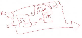
I've built something to power my amp on and off but it's really simple. I use the 5v supply for my r pi and a latching relay, though I only show one leg, which is ok with a better 5v supply.
I just use a pi gpio pin to turn on the relay and trigger it via whatever event I want.
I've built something to power my amp on and off but it's really simple. I use the 5v supply for my r pi and a latching relay, though I only show one leg, which is ok with a better 5v supply.
I just use a pi gpio pin to turn on the relay and trigger it via whatever event I want.
Attachments
Hi Charlie,
I might be interested in this later on. Perhaps there are simpler sensor methods than adding an extra DAC? This page has ideas for 'sound activated' processing - in this case to trigger recording. The script-based methods could be generally adaptable to trigger GPIO activity as @Speaky suggested. ...just a thought... All the best!
I might be interested in this later on. Perhaps there are simpler sensor methods than adding an extra DAC? This page has ideas for 'sound activated' processing - in this case to trigger recording. The script-based methods could be generally adaptable to trigger GPIO activity as @Speaky suggested. ...just a thought... All the best!
I just use a pi gpio pin to turn on the relay and trigger it via whatever event I want.
Sure, but can you use the presence or absence of an audio stream to trigger the GPIO pin? That is the point of my setup. Audio on? Amp turns on. No more audio? Amp turns off.
Hi Charlie,
I might be interested in this later on. Perhaps there are simpler sensor methods than adding an extra DAC? This page has ideas for 'sound activated' processing - in this case to trigger recording. The script-based methods could be generally adaptable to trigger GPIO activity as @Speaky suggested. ...just a thought... All the best!
Maybe you missed it... but there is a DAC onboard the Pi. It's not very good quality (only about 10-11 bit) and I wouldn't use it for audio output, so I figured why not put it to use for this purpose?
This is all very simple to do using the new LADSPA plugin I put together. I didn't find anything that used the audio stream as the basis for triggering external signals that fit my needs, so I DIY'd something that both works for me, and should be versatile enough for many audio related applications like those I touched on in my post above.
Maybe you missed it...
Yes, I did miss that important detail! 😛 ...sounds like you're having fun! 🙂
I understand, although you were talking about getting another dac for more channels.
But, consider this...
Or...
If this was a little pc, I've used audio ports like you're describing, but this is an Arduino-type with gpio built in.
But, consider this...
- write a filter to generate an audio square wave, occupy a channel
- create a rectifier circuit
- add gain
- attach to one of two audio outputs
Or...
- write a filter to trigger a gpio pin, have 15 or so left and no CPU usage and 3v on state
If this was a little pc, I've used audio ports like you're describing, but this is an Arduino-type with gpio built in.
I understand, although you were talking about getting another dac for more channels.
But, consider this...
- write a filter to generate an audio square wave, occupy a channel
- create a rectifier circuit
- add gain
- attach to one of two audio outputs
Or...
- write a filter to trigger a gpio pin, have 15 or so left and no CPU usage and 3v on state
If this was a little pc, I've used audio ports like you're describing, but this is an Arduino-type with gpio built in.
The way I look at it, the Raspberry Pi IS a little PC! 🙂 Well, OK it does have some IO pins available, too. 😉 I already completed the list of things above, so I am all set there and the ball is rolling for me. Your way is certainly a more than valid alternative.
I should mention that I don't always use a Pi. For instance I have a small PC running Ubuntu that I am building into a system. My approach will work on that platform, too, using one of the myriad audio output channels (there is onboard 7.1+2 analog audio out). Alas, no GPIO pins available there, so your way wouldn't' work.
Anyway, if you can share some C/C++ code for toggling the GPIO pin, or point me to some code like that I would be interested in seeing what is involved.
I just use the Pi like a little computer and have never used the GPIO pins. I did that on an Arduino when there was not much else to work with... but the R-Pi is a completely different league.
Last edited:
Hi,
This looks pretty straightforward. I've only used python, so beware.
Low Level Programming of the Raspberry Pi in C | Pieter-Jan.com
If you get a filter going I'd sure be interested. My audio card uses some of the pins but i've got plenty left over. What I'd really like is to have it read an environment variable or file or... so I can manually turn it off or on and override/use the auto-music-detect at will. That'd be cool.
What I was planning was a python daemon triggered by a filter. After continuous triggering for a bit the daemon would turn on power. After not hearing from the filter for a while the daemon would turn off the power.
Last edited:
Some code like this could be used to set a GPIO pin to high or low, depending on what the audio is doing, from within a LADSPA plugin.
This is like the Arduino. It's about a simple as it gets, if indeed that is all the code you need. I will look into this a little more.
Code:
#include "RPI.h"

int main(
{
  if(map_peripheral(&gpio) == -1)
  {
    printf("Failed to map the physical GPIO registers into the virtual memory space.\n");
    return -1;
  }

  // Define pin 7 as output
  INP_GPIO(4);
  OUT_GPIO(4);

  while(1)
  {
    // Toggle pin 7 (blink a led!)
    GPIO_SET = 1 << 4;
    sleep(1);

    GPIO_CLR = 1 << 4;
    sleep(1);
  }

  return 0;
}
This is like the Arduino. It's about a simple as it gets, if indeed that is all the code you need. I will look into this a little more.
You all have too much fun! Learning a lot from following along. I need to get another board so I was lookin around for alternatives since I already have a pi2. The Odroid C1+ looks really interesting with Gigabit Ethernet and should be coming out shortly. What do you think? ODROID-C1+ Board is an Upcoming Upgrade to ODROID-C1 Board
Well, whether you want to use a GPIO pin or my method that requires one $50 cent op amp (an LM358) and a few resistors, you still need the basic transistor-driving-relay circuit to switch the relay, and the flyback protection on the coil.
So I could design a PCB so that you could connect into the circuit at the resistor feeding current to the base of the transistor if you want to use the GPIO pin method (leaving the rest of the board unpopulated) or go the full monty and add the other stuff as well if you are using my approach.
I could easily write up a separate plugin that switched the GPIO pin instead of outputting a signal to an audio port. This doesn't seem like a big deal on the surface of it.
If the playback chain opens the card upon reception of the audio data, there are numerous indicators of playback - e.g. alsa chain can be fitted with a file plugin starting a script directly operating the GPIO.
BTW, in separate networked speakers, what is the audio samples transportation protocol which keeps both the channels synchronized (independent clock domains etc.) in order to preserve the stereo field?
BTW, in separate networked speakers, what is the audio samples transportation protocol which keeps both the channels synchronized (independent clock domains etc.) in order to preserve the stereo field?
If the playback chain opens the card upon reception of the audio data, there are numerous indicators of playback - e.g. alsa chain can be fitted with a file plugin starting a script directly operating the GPIO.
BTW, in separate networked speakers, what is the audio samples transportation protocol which keeps both the channels synchronized (independent clock domains etc.) in order to preserve the stereo field?
I'm not planning to do anything in ALSA. That just seems way too complicated. Anyway, that wouldn't work in my case because the card is open all the time in my application, even when there is no audio coming in.
The way I do it, you are actually monitoring the audio stream for its amplitude, so for instance even if there is background noise you can put the on-off threshold above the level of the noise and it will still turn off when there is no "music" signal.
RTSP is the answer to your question #2.
- Home
- Source & Line
- PC Based
- LADSPA plugin programming for Linux audio crossovers