hi
Story of this Lab Supply I built goes back 10 years.
This dual tracking supply has served well ever since.
It has some features you can't easily do with the standard LM317/LM337 supply circuit.
------------------------
- One potentiometer to set Main positive/negative output voltage
- Output voltage span is +/- 0.0 to more than 19.5 Volt at +/-20 Volt input
- I guess voltage drop is about 0.2 Volt at 200mA.
- Output transistors BD241/BD242
( the normal LM317/337 setup does not give lower than 1.25V
and the voltage drop is at least 2.5 Volt )
I have for control totally 3 potentiometers:
- Main voltage level, coarse, effects both V+ and V-
- Fine adjust voltage level, same effect V+ and V-
- Fine adjust negative voltage to match V+ exactly
I plan to add a simple current overload protector
even though I have managed without this, during my experiments these 10 years.
Main use for this low power version I have is my preamplifier and Op-Amp circuits try out.
And the transformer is the only thing
that once did set limit for output voltage / current.
Rating: 2x15VAC, 15VA gives max ~20.5V DC and 300mA.
-----------------------------
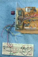
Attachment #1:
An overview of my supply.
I live alone without children.
So I haven't bothered to put in a case.
Story of this Lab Supply I built goes back 10 years.
This dual tracking supply has served well ever since.
It has some features you can't easily do with the standard LM317/LM337 supply circuit.
------------------------
- One potentiometer to set Main positive/negative output voltage
- Output voltage span is +/- 0.0 to more than 19.5 Volt at +/-20 Volt input
- I guess voltage drop is about 0.2 Volt at 200mA.
- Output transistors BD241/BD242
( the normal LM317/337 setup does not give lower than 1.25V
and the voltage drop is at least 2.5 Volt )
I have for control totally 3 potentiometers:
- Main voltage level, coarse, effects both V+ and V-
- Fine adjust voltage level, same effect V+ and V-
- Fine adjust negative voltage to match V+ exactly
I plan to add a simple current overload protector
even though I have managed without this, during my experiments these 10 years.
Main use for this low power version I have is my preamplifier and Op-Amp circuits try out.
And the transformer is the only thing
that once did set limit for output voltage / current.
Rating: 2x15VAC, 15VA gives max ~20.5V DC and 300mA.
-----------------------------
Attachment #1:
An overview of my supply.
I live alone without children.
So I haven't bothered to put in a case.
Attachments
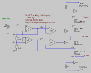
Simplified and Principal circit diagram
hi
Here is the simplified circuit diagram.
If you have some good DIY knowledge
you will be able to build this from diagram
and add those components necessary for correct working circuit.
But I will be back with the full circuit
and some more about details, later.
I have set it up in my circuit simulator, using precision Op-Amplifiers OP07.
This is why I call this project LabSupply07.
Analog Devices OP07 - Ultralow Offset Voltage Operational Amplifier
This one is good for the job.
Yet, it does not cost too much. It works extremely well in my Simulations.
lineup
Attachments
the easiest way to do a dual tracking supply is to use one reference and two buffers -- one inverting -- and one non-inverting. I have used a dual DAC as well.
you have some gymnastics to consider when designing the compensation loops for the positive and negative supplies but these are certainly not difficult to tackle.
you have some gymnastics to consider when designing the compensation loops for the positive and negative supplies but these are certainly not difficult to tackle.
jackinnj said:the easiest way to do a dual tracking supply
is to use one reference and two buffers -- one inverting -- and one non-inverting.
just like i did 😉
See diagram a few centimeters above here!
The compensation details I have used
is one of those details I talk about in my posts.
lineup
I think that your supply, technically is not "tracking". The objective for tracking is to have 0V in the middle of the +- outputs at ALL times Ripple rejection is also improved. Idealy, what you want is if one supply suddenly went to some value because of an overload, the other would "track" that supply but be of opposite polarity.
A slightly better design would be to make the reference of the other rail the voltage divided value of the set rail multiplied by -1.
I'm probably not making any sense.
A slightly better design would be to make the reference of the other rail the voltage divided value of the set rail multiplied by -1.
I'm probably not making any sense.
😎
A very good one, QSerraTico_Tico
thanks!
I would build that one, if I hadnt good working Lab Supply already.
As described above.
-----------------------------------
My idea and circuit is simple, should be easy to build,
( use 1 Quad LM324 Opamp like I did )
and my lab supply delivers minimum
+/- 2 x 0.005 -> 19.5 Volt, from an +/-20.5V unreg supply.
With trimpot adjust for 100% symmetrical Voltages out.
So why & when can we need low voltages down to close +/- 2 x 0.005 V ?
LM317 / LM337 are limtied to 1.25 V out.
Well, I have done some work with amplifiers for 2 x 1.5 battery cells supply.
When such a battery is beginning to get empty,
the voltage delivered can approach downto 1.0 Volt.
So I have had some good use for this Lab Supply.
It depends on your needs. But sure does not hurt to have this feature.
Along with a drop out voltage, that is <1.0 Volt.
( at normal work, normal currents, actually as low a drop out as < 0.2-0.3 Volt )
My power supply for this circuit is dual trafo, ~20.5 VDC, unreg.
lineup
lineup said:So why & when can we need low voltages down to close +/- 2 x 0.005 V ?
LM317 / LM337 are limtied to 1.25 V out.
Not necessaily so, you can bias the adust pin of the LM317 or LM337 to bring the lowest level down to 0.000 volts -- see National Semi's website for the "how to".
Lineup Lab Supply07 - final version
yes,
of course,
I know my very easy circuit is not the final work on Lab Supply.
Besides, what I show is simplified version.
Just not to confuse those being the process to start DIY audio.
If anyone wants to get my full schematic of latest version
... just ask!
I can post a full scheme of my setup showing terrific precision in MultiSim,
using OP07 operational amplifiers.
Including my comp caps for stabilization & trimpots for 0.01% tracking 😎
Regards 🙂 lineup
I, personally, wouldn't mind taking a peek at the full schematic of your revered lab supply 🙂
And i don't think anyone else would mind, if only to see the complexity (or lack of it) needed for such accuracy
And i don't think anyone else would mind, if only to see the complexity (or lack of it) needed for such accuracy
- Status
- Not open for further replies.
- Home
- Amplifiers
- Power Supplies
- LabSupply07 - Dual Tracking Circuit