hi all,
A couple of weeks ago, I finished (that's what I hoped...) my version of the la bohème MC phono stage .
With my limited spare time, it took me nearly a year. I build several incarnations with then optimised circuiting, component placing and the like. There was a marvellous sounding in-between version, that I took and made the final version of with additional ‘improvements’.
Well, actually not.
The final version sounds not that outstanding, and I don’t find the path back, meaning there are too many possible pathes. So I could do very well with some input from the more experienced members around.
Compared to other decent phono stages(1), some friends and me found the following to be true: It was almost on par in the bass region, but lacked significantly clarity in the mids and resolution as well as sweetness in the highs.
So, things to discuss might be:
· Physical incarnation, meaning circuiting, component placing and the like.
· Improving circuit details (different versions for CS, alternative riaa circuiting and the like)
· Other psu options. Batteries seem to loose their state of being the optimal power feeders. So other options like shunt regulation, super-reg or passive filtering may reveal even better performance
· Having another output stage, maybe discrete
I’ve some future plans for phono stages, but decided to work on this one till I get some decent results.
Some considerations I’ve made so far:
The good sounding version was the MKIII (with two 2sk369 and one 2sk369 as CS), final version is MKIIIb (see linked page above).
· Paralleling FET’s degrade sound in comparison to SE. On the other hand, this is used by N.Pass, for instance
· It is better to cascode every single FET, not 3 at once
· The CS with BF246 degrade sound (If at all, how could that be? Lower gm of fet’s?)
· High capacitve RIAA sounds worse ( <-> lower resistance)
· No ‘impedance (meaning resistance) linearization’ for the opa627 inputs in final version
· Higher feedback in output stage sounds worse
· Hidden degraded parts (we’d had worst case here)
· Poor physical design
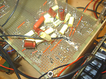
The posted photo shows the input stage of the last version, the large caps in the background are mundorfs for the riaa, meanwhile, they have been replaced with much better soundig EMZ-caps (the orange blocks from thel-audio).
I’ll make more close-up photographs while working on that thing…
So I invite you to drop in and discuss, give hints or ask questions. It would be a nice thing to know at the end how close one can drive Klaus’ great design to the mentioned phono stages… Or maybe beyond…
Thanks a lot,
Rüdiger
(1) Schäfer emitter basis HD , Blue Amp , phono part of horch arbiter

A couple of weeks ago, I finished (that's what I hoped...) my version of the la bohème MC phono stage .
With my limited spare time, it took me nearly a year. I build several incarnations with then optimised circuiting, component placing and the like. There was a marvellous sounding in-between version, that I took and made the final version of with additional ‘improvements’.
Well, actually not.
The final version sounds not that outstanding, and I don’t find the path back, meaning there are too many possible pathes. So I could do very well with some input from the more experienced members around.
Compared to other decent phono stages(1), some friends and me found the following to be true: It was almost on par in the bass region, but lacked significantly clarity in the mids and resolution as well as sweetness in the highs.
So, things to discuss might be:
· Physical incarnation, meaning circuiting, component placing and the like.
· Improving circuit details (different versions for CS, alternative riaa circuiting and the like)
· Other psu options. Batteries seem to loose their state of being the optimal power feeders. So other options like shunt regulation, super-reg or passive filtering may reveal even better performance
· Having another output stage, maybe discrete
I’ve some future plans for phono stages, but decided to work on this one till I get some decent results.
Some considerations I’ve made so far:
The good sounding version was the MKIII (with two 2sk369 and one 2sk369 as CS), final version is MKIIIb (see linked page above).
· Paralleling FET’s degrade sound in comparison to SE. On the other hand, this is used by N.Pass, for instance
· It is better to cascode every single FET, not 3 at once
· The CS with BF246 degrade sound (If at all, how could that be? Lower gm of fet’s?)
· High capacitve RIAA sounds worse ( <-> lower resistance)
· No ‘impedance (meaning resistance) linearization’ for the opa627 inputs in final version
· Higher feedback in output stage sounds worse
· Hidden degraded parts (we’d had worst case here)
· Poor physical design
The posted photo shows the input stage of the last version, the large caps in the background are mundorfs for the riaa, meanwhile, they have been replaced with much better soundig EMZ-caps (the orange blocks from thel-audio).
I’ll make more close-up photographs while working on that thing…
So I invite you to drop in and discuss, give hints or ask questions. It would be a nice thing to know at the end how close one can drive Klaus’ great design to the mentioned phono stages… Or maybe beyond…
Thanks a lot,
Rüdiger
(1) Schäfer emitter basis HD , Blue Amp , phono part of horch arbiter
Hi Ruediger,
although we already had email exchange on a bilateral basis I am happy you posted you questions on the forum and I hope we will have some input from the experts over here.😀
I would like to comment a few of your points:
Of course this preamp is not a weekend project and it took me almost two years for development and I also had to deal with some drawbacks. In fact the final circuit might be considered a kind of an overkill, but my amp never was meant for commercial purpose but as a mayor hobby project which is now working really nicely.
Obviously you had one intermediate version that was working satisfactorily. So the question is what went wrong after that. 😕
Please excuse that I first ask some basic questions:
Did you make sure that the input impedances (R and C) of the different phono stages were identical when you did the listening tests.
Did you make sure that all the voltages were set correctly. I once had a disappointing listening test with my preamp when I did not realize that the supply for the input stage cascode was down to about 3V.
Basically my concept is meant for a symmetrical input. In case you drive the input non-symmetrically the second input has to grounded properly.
Did both channels perform equally (bad) ?
In my experience damage of the output transformers is unlikely. But have you double checked that all the coils and the grounding are connected properly.
From your unsatisfying listening results I would start with the following procedures:
Though I double checked the values of the RIAA network on my web site you should ensure by own measurements whether the network fits the RIAA curve in your application.
Does the output stage work properly. The composition op amp circuits tend to oscillate at several MHz due to the extreme bandwidth and need careful wiring. Please check with a suitable scope whether you have oscillation problems.
Greetings Klaus
Hi Klaus,
...and this overkill is quite appealing, I think...
I is indeed wise to solve the problems first and then discuss possible improvements.

So I would need a sweep or something like that. Should be possible to find a *.wav file on the net.

The op-amps only get hand-warm, if at all, the CFP amps perhaps a bit warmer. I made some effort and thinking for short pathes, but then... who knows?
I will take some photos next time I .
.
thanks a lot for your time and effort,
Rüdiger
KlausB said:In fact the final circuit might be considered a kind of an overkill, but my amp never was meant for commercial purpose but as a mayor hobby project which is now working really nicely.
...and this overkill is quite appealing, I think...
I is indeed wise to solve the problems first and then discuss possible improvements.
I have 1k - 2x 500R - for Denon103 here. I did not add any C.KlausB said:Did you make sure that the input impedances (R and C) of the different phono stages were identical when you did the listening tests.
I charge the batteries regulary. I will check if there's another mistake. It is indeed easily audible when the batteries need recharging.KlausB said:
Did you make sure that all the voltages were set correctly. I once had a disappointing listening test with my preamp when I did not realize that the supply for the input stage cascode was down to about 3V.
YesKlausB said:
Did both channels perform equally (bad) ?
Uh...oh....KlausB said:
Though I double checked the values of the RIAA network on my web site you should ensure by own measurements whether the network fits the RIAA curve in your application.
So I would need a sweep or something like that. Should be possible to find a *.wav file on the net.
My scope can cope with freqs up to 10Mhz. Sufficient or not?KlausB said:
Does the output stage work properly. The composition op amp circuits tend to oscillate at several MHz due to the extreme bandwidth and need careful wiring. Please check with a suitable scope whether you have oscillation problems.
The op-amps only get hand-warm, if at all, the CFP amps perhaps a bit warmer. I made some effort and thinking for short pathes, but then... who knows?
I will take some photos next time I
.thanks a lot for your time and effort,
Rüdiger
Hi,
😡
Well, I checked again, the scope showed nothing, but I regonized that the opamps get quite warm after a while (> 15 min) and the sound gets worse.
The only difference between the good working version: The wires to the OPT have now the same length, the psu-wires form now a bus topology, the working version had single wires from terminal to each op-amp. Decoupling Caps are Elna 220uF, most on top, and 150nF Foil (ERO 1813 soldered directly at the pins) all at the underside, see photo (new version)
After checking I installed the 1k5/2k resistance network on the input s of the opa627 from MKIII-version (See http://www.diyaudio.com/forums/showthread.php?postid=436830#post436830 why) but then the thing truly started to oscillate: opamp got hot (only switched on a few seconds) and it sounded like noise on the short wave radio band.
So it appears to me that 1) bus-topology does not work here 2) I maybe use wrong or non-optimal caps.
A look at the underside:
KlausB said:
Does the output stage work properly. The composition op amp circuits tend to oscillate at several MHz due to the extreme bandwidth and need careful wiring. Please check with a suitable scope whether you have oscillation problems.
😡
Well, I checked again, the scope showed nothing, but I regonized that the opamps get quite warm after a while (> 15 min) and the sound gets worse.
The only difference between the good working version: The wires to the OPT have now the same length, the psu-wires form now a bus topology, the working version had single wires from terminal to each op-amp. Decoupling Caps are Elna 220uF, most on top, and 150nF Foil (ERO 1813 soldered directly at the pins) all at the underside, see photo (new version)
After checking I installed the 1k5/2k resistance network on the input s of the opa627 from MKIII-version (See http://www.diyaudio.com/forums/showthread.php?postid=436830#post436830 why) but then the thing truly started to oscillate: opamp got hot (only switched on a few seconds) and it sounded like noise on the short wave radio band.
So it appears to me that 1) bus-topology does not work here 2) I maybe use wrong or non-optimal caps.
A look at the underside:
Hi Ruediger,
Most likely you still have problems with the output stage though you already took care to prevent oscillating. Remember that the gain-bandwidth-product of the composite op amp is beyond 1000 MHz (!!) according to the BB datasheets and thus the wiring is very sensible. Maybe, your circuit does not constantly oscillate, but suffers from oscillation bursts during operation.
From my experience a careful star wiring of all power supply leads is essential. For decoupling I used small WIMA MKS caps to ensure the shortest connections possible.
The OPA 603 has an idle current of 20mA. Hence this op runs quite hot during operation because it dissipates around 0.5 watts. The OPA 627s must stay cool.
In my MKIIIb version I omitted the 1.5k/2k input resistors, because the input impedances are so low (20 ohms at the inverting input) and a high capacitive load is given at the non-inverting input from the RIAA network. So the effects of the input capacitances may be neglected. 🙄
In my application I successfully suppressed any oscillation tendencies by soldering the two 10nF RIAA caps of each channel directly to the non-inverting input pin of the OPA 627 and to ground. 😉
I even replaced the tame OPA627 by the faster OPA637
  and it works fine.
Regards
KlausB
Most likely you still have problems with the output stage though you already took care to prevent oscillating. Remember that the gain-bandwidth-product of the composite op amp is beyond 1000 MHz (!!) according to the BB datasheets and thus the wiring is very sensible. Maybe, your circuit does not constantly oscillate, but suffers from oscillation bursts during operation.
From my experience a careful star wiring of all power supply leads is essential. For decoupling I used small WIMA MKS caps to ensure the shortest connections possible.
The OPA 603 has an idle current of 20mA. Hence this op runs quite hot during operation because it dissipates around 0.5 watts. The OPA 627s must stay cool.
In my MKIIIb version I omitted the 1.5k/2k input resistors, because the input impedances are so low (20 ohms at the inverting input) and a high capacitive load is given at the non-inverting input from the RIAA network. So the effects of the input capacitances may be neglected. 🙄
In my application I successfully suppressed any oscillation tendencies by soldering the two 10nF RIAA caps of each channel directly to the non-inverting input pin of the OPA 627 and to ground. 😉
I even replaced the tame OPA627
by the faster OPA637 and it works fine. Regards
KlausB
There is hope...
Hi,
there is light at the end of the tunnel, and I don't think it's a train coming rapedly closer...
I rebuild the output stage, starwired supply leads, took other decoupling caps (stayed with the cerafines, but took small 'naked' siemens mks in parallel) and changed physical layout a bit.
I think I'm done with the output.
Then i desolderd 446R (of riaa filter) and put in an trim pot of 1k. Subjektivly, things improved a lot, and the pot measures 506R now.
In fact, it is quite an enjoyable thing now.
That leads to the conclusion, that I absolutly have to finetune the filter by means of measurement.
1) Can I get by with compterbased tools, as i only have an DMM and an old 10Mhz scope?
2)Additionally, i'm not sure which components are responsable for which curvenodes.
What would - for instance - happen, if I increase C = 693nF up to, say, 700nF?
Ruediger
Hi Klaus,
.... better later than never .... I re-open your project .....
Klaus, my I ask you:
In your concept (MKIIIb) you "insist" to use the duo OPA627 (not the OPA637) and with a triple choice LM6181 or LT1206 or AD811.
In your experience now: is the duo OPA637 & LT1206 a winner (without problems like osci. offset e.o. ...).
Thanks for your practical feed back in 2009...
(my PSU is done)
Karel
KlausB said:
I even replaced the tame OPA627
.... better later than never .... I re-open your project .....
Klaus, my I ask you:
In your concept (MKIIIb) you "insist" to use the duo OPA627 (not the OPA637) and with a triple choice LM6181 or LT1206 or AD811.
In your experience now: is the duo OPA637 & LT1206 a winner (without problems like osci. offset e.o. ...).
Thanks for your practical feed back in 2009...
(my PSU is done)
Karel
carolus said:Hi Klaus,
In your concept (MKIIIb) you "insist" to use the duo OPA627 (not the OPA637) and with a triple choice LM6181 or LT1206 or AD811.
In your experience now: is the duo OPA637 & LT1206 a winner (without problems like osci. offset e.o. ...).
Thanks for your practical feed back in 2009...
(my PSU is done)
Karel
Hi Karel,
sorry for my late response. In the meanwhile I also switched to the OPA 637. If the OPA 603 is not available the best substitute in my experience is the AD811. The other current feedback op amps sounded more harsh.
However, it is a couple of years ago that I built my phono preamp. Today I probably would design it differently.
I made very good experience with input transformers, paralleling the input fets turned out to be a problem, because the RIAA caps needed to be very big. The KP capacitors of the first version sounded better than the large Mundorf caps.
A friend of mine built my phono stage but asymmetrical and no output transformer. We agreed it sounded somehow better. 😀
Cheers
KlausB
La boheme
Hi Klaus,
Nice to read you (after several PM) ....
After a couple test with the tandem "627 & 603" (on pcb) .... Hélas, I discard the solution "composit OPA" (after two run away and termal expl.) ..... a complex situation.
I stay (at this moment) for your " input sextet 369 & PSU" .... and tray (to find) an "other" and safer concept output.
I appreciat your (friends) input about the real possibility for "asymetrical and no OPT" ....
Allez, salukes ... and I listen to a white CéDé (not black vinyl) Bach BWV12 ....
Cheers.
Karel
La Boheme
Hi Klaus,
I sent you a PM.
I hope to find a good "connector" ....
Allez, salukes.
Cheers & best regards from Brussels.
Karel
KlausB said:
A friend of mine built my phono stage but asymmetrical and no output transformer. We agreed it sounded somehow better. 😀
KlausB
Hi Klaus,
I sent you a PM.
I hope to find a good "connector" ....
Allez, salukes.
Cheers & best regards from Brussels.
Karel
- Status
- Not open for further replies.
- Home
- Source & Line
- Analogue Source
- La Bohème