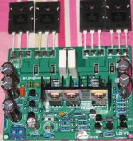
The new version I test it will is the top level of the power amplifier simulation power amplifier.
It USES four to power tube. Positive, the reverse side.
Tests used only 2 to transistor output.
It will be a perfect power amplifier.

It USES four to power tube. Positive, the reverse side.
Tests used only 2 to transistor output.
It will be a perfect power amplifier.
Attachments
Last edited:
it is about 250W 8R (+ -70V)
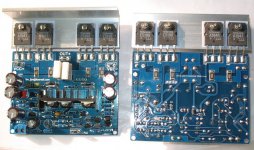
Four double transistor of the power output. Each circuit board.
Each level of all use CFP.
Four double transistor of the power output. Each circuit board.
Each level of all use CFP.
Interesting! Can't see a thermal sensor on the heatsink.
You say temperatures are very low - how did you bias the outputs?
And again can we see a schematic please?
You say temperatures are very low - how did you bias the outputs?
And again can we see a schematic please?
ljm_ljm,
How many versions of the L20 are there? I saw a L20, V7, V9 and others on ebay
Which one is better?
And why?
Thanks.
How many versions of the L20 are there? I saw a L20, V7, V9 and others on ebay
Which one is better?
And why?
Thanks.
Hi Sakis
No, OP says just 2 pairs now for testing - turn the board over and fit another 2 pairs on that side (later).
'Sure makes it a tight board, though 🙂
No, OP says just 2 pairs now for testing - turn the board over and fit another 2 pairs on that side (later).
'Sure makes it a tight board, though 🙂
thanks Ian ( how are you by the way ? )
still this doesn't look very good 70 volts are just enough for 250W.... and then of course pcb needs to be redesigned to handle the power and accommodate supporting circuits such is zobel with inductor , VI limiters , any other limiter and Dc protection
still this doesn't look very good 70 volts are just enough for 250W.... and then of course pcb needs to be redesigned to handle the power and accommodate supporting circuits such is zobel with inductor , VI limiters , any other limiter and Dc protection
Interesting! Can't see a thermal sensor on the heatsink.
You say temperatures are very low - how did you bias the outputs?
And again can we see a schematic please?
It's CFP - the sensor will be on the driver heatsink, I guess.
Brian.
CFP output
Ohhh...I thought you liked P3a with CFP, even in bridgemode, Sakis - anyway, I'm well and I hope business is improving for you, this Christmas
My best wishes to your family and I hope your son is growing and learning to solder now...😀 You will make more profit when he gets the hang of it and you can take a break and DIY some more. I think we need to hear another P3a comparison this Christmas...anything in mind? 😉
ljm_ljm,
How many versions of the L20 are there? I saw a L20, V7, V9 and others on ebay
Which one is better?
And why?
Thanks.
L20 Now to the sale of the VER7 and VER9 version.
VER9 used the MOSFET driver
aaa...marvelous...250 W cfp ..... that will make a perfect oscillator !!!!!
yes. it is a MOSFET+ BJT OUTPUT CFP.
AND CFP INTPUT..
It is very stable. Reliable.
L20 Now to the sale of the VER7 and VER9 version.
VER9 used the MOSFET driver
Thanks for replying.
What are the benefits of mosfet vs. bipolar inputs on this particular board?
Do the output transistors behave more linearly with the mosfets vs. the bipolar inputs?
Or is it a matter of lower distortion?
Sorry for all the questions. I have to make a choice soon.
Last edited:
Ohhh...I thought you liked P3a with CFP, even in bridgemode, Sakis - anyway, I'm well and I hope business is improving for you, this Christmas
My best wishes to your family and I hope your son is growing and learning to solder now...😀 You will make more profit when he gets the hang of it and you can take a break and DIY some more. I think we need to hear another P3a comparison this Christmas...anything in mind? 😉
well Ian ...is still believe that a properly made CFP is the best way to go for class AB Bjt domestic application ....
Repairing an average of 400 amplifiers per year i may tell you that never seen a properly working CFP with more than 2 pairs of BJT outputs especially at this rate of power ...all attempts in the past failed and if any working only made for limited bandwidth to avoid oscillations ....
Just a few days ago i ve seen Italian design of CFP with 2pairs per ch. while each and every one of them had its own driver ( 4 drivers totally )...... nightmare !!! imagine miller caps of hundreds of picofarad in both drivers and outputs to stabilize ...
obviously nice idea but bad approach plus that its almost impossible to repair if you don't have proper transistors plus properly matched ...
The only possible way to stabilize is to use fast drivers and slow outputs but after that the all design is degraded regarding sonic performance ...May good enough and stable for pro use but out of the question for hifi or above applications ...
My 2 cents
- Home
- Amplifiers
- Solid State
- L20 V8