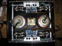
I removed the supplied input capacitors on my monoblock builds and the sound is significantly better. But removing the capacitors is not a good idea if there is any DC on the input signal. Otherwise, the amps are stock standard and I have fitted speaker protection modules. I used new toroids which give +/-56V rails which for me are a lot safer than the +/-73V rails I had with the first toroids. Of course the power is lower but I never use more than about 20W on the loudest passages with my 92db speakers. The L20V9 really does sound very realistic, the bass end is well controlled and the overall sound is very smooth. It could be a little more detailed at the top end when I compare it to my 300B 60W monoblocks but they are a hard act to follow. I'm using 4x10,000uf on each power supply rail plus 10x22uf wound foil caps on each rail. I feel that this 220uf of foil caps on each rail cleans up the top end a little and have used the same idea on other builds. I am using massive heatsinks which are complete overkill and never seem to warm up. However, when the amps have been on for a few hours they do seem to sound a little more detailed and the layering is improved slightly.
Thank you for this review but I am still doubt with other comment regarding the stability of unit but I will try on with low voltage +/- 25VAC.
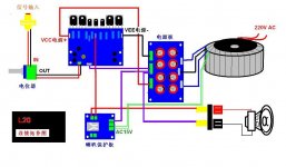
Hi, I am looking for the schematic diagram for the new LJM L20 V9 Power Amp ???????
Attachments
Last edited:
Low pass audio filter placed after amplifier - All About Circuits Forum
by removing the input capacitor(10uf) the amplifiers started to sound
and quite nice,i should remove the 10k resistor as well
- and of course Replace the 2k2 resistor with a COIL (inductor) and C2 to ,with the calculated value for the 24,5 - 25khz LowPass filter 😛
and bring the input to aprox 6-8V preamplifaction,i dont know the upper limit
that will be normal for high end preamp
the 100k should stay in place because it brings preamp to required input impedance
sO HIGH PASS filter only after amplifier and !! Not Before
- also replaced 1n4007 with ultrafast 35ns diodes ,because 1n4007 limited speed will act as a filter for transistor switching

This would appear to be true for the Silicon Chip ULD Mk2&3 mudules as well.

L20V9
There is no need to touch any other components when the input coupling capacitor is removed. It just means that the the sound will improve and the LF responce will extend down to DC. If there is any DC on the input signal from the source then that would be a problen as the DC at the L20V9 speaker output terminal would no longer be zero and if more than 50mV then speaker damage could occur. My L20V9 PCB's have been working very well now for a couple of months. They are stock standard apart from removal of the input capacitor and they do not show any signs of instability. The heat sinks I am using are too big and don't get warm and it takes quite a few hours for the amps to sound nice at the top end. This might be because the output devices a running too cold or maybe not.
There is no need to touch any other components when the input coupling capacitor is removed. It just means that the the sound will improve and the LF responce will extend down to DC. If there is any DC on the input signal from the source then that would be a problen as the DC at the L20V9 speaker output terminal would no longer be zero and if more than 50mV then speaker damage could occur. My L20V9 PCB's have been working very well now for a couple of months. They are stock standard apart from removal of the input capacitor and they do not show any signs of instability. The heat sinks I am using are too big and don't get warm and it takes quite a few hours for the amps to sound nice at the top end. This might be because the output devices a running too cold or maybe not.
L20V9
I forgot the bit about the Silicon Chip amps. I have built these amps and the same comments apply about the input capacitor. I suppose it is wise to have an input capacitor especially if you sometimes use the amp with someone elses equipment. In that case just use a good quality capacitor preferably not an electrolytic type. I did use 10uf Mundorfs for a while but they are big and have to be mounted off board (with some good shielded wire in my case).
I forgot the bit about the Silicon Chip amps. I have built these amps and the same comments apply about the input capacitor. I suppose it is wise to have an input capacitor especially if you sometimes use the amp with someone elses equipment. In that case just use a good quality capacitor preferably not an electrolytic type. I did use 10uf Mundorfs for a while but they are big and have to be mounted off board (with some good shielded wire in my case).
L20V9.2
Good morning brother. I have some nice Ducati MKPP motor start caps that might go all-right. Once again they are large, so would need to be mounted offboard. However, the Silicon chip uldMk2 build instructions state that there is a big difference in impedance at the low frequency end, i.e. the electro has less impedance, lots less. I am using a Yamaha DVD S659 as an input for my CD'S. I will need to look into the impedance requirements of it's output to make this decision. Perhaps the lower impedance is only required for phono inputs or vice versa. I need to do a bit more reading I think.
Thankyou for your replies. I will let you all know what happens when I get my kit. Cheers and bye for now. Jack
I forgot the bit about the Silicon Chip amps. I have built these amps and the same comments apply about the input capacitor. I suppose it is wise to have an input capacitor especially if you sometimes use the amp with someone elses equipment. In that case just use a good quality capacitor preferably not an electrolytic type. I did use 10uf Mundorfs for a while but they are big and have to be mounted off board (with some good shielded wire in my case).
Good morning brother. I have some nice Ducati MKPP motor start caps that might go all-right. Once again they are large, so would need to be mounted offboard. However, the Silicon chip uldMk2 build instructions state that there is a big difference in impedance at the low frequency end, i.e. the electro has less impedance, lots less. I am using a Yamaha DVD S659 as an input for my CD'S. I will need to look into the impedance requirements of it's output to make this decision. Perhaps the lower impedance is only required for phono inputs or vice versa. I need to do a bit more reading I think.
Thankyou for your replies. I will let you all know what happens when I get my kit. Cheers and bye for now. Jack
There is no need to touch any other components when the input coupling capacitor is removed. It just means that the the sound will improve and the LF responce will extend down to DC. If there is any DC on the input signal from the source then that would be a problen as the DC at the L20V9 speaker output terminal would no longer be zero and if more than 50mV then speaker damage could occur. My L20V9 PCB's have been working very well now for a couple of months. They are stock standard apart from removal of the input capacitor and they do not show any signs of instability. The heat sinks I am using are too big and don't get warm and it takes quite a few hours for the amps to sound nice at the top end. This might be because the output devices a running too cold or maybe not.
Me again! Can you tell me what you are using for a heatsink? I have the Conrad MF20-75 @ 0.55 degC/W for 80 degC rise type left over from the ULD. Are you using the MF30-75? 0.39____
L20V9
I am using the Conrad MF35-151.5 heatsink. There is no way known that I would ever require a heatsink this big at the powers I use. I doesn't even seem to rise above ambient at idle. I used this size it as it forms part of the cabinet/chassis of the monoblocks I built.
I am using the Conrad MF35-151.5 heatsink. There is no way known that I would ever require a heatsink this big at the powers I use. I doesn't even seem to rise above ambient at idle. I used this size it as it forms part of the cabinet/chassis of the monoblocks I built.
4,7 kohm across the original was to much. Ordered 2 x BD 679 A. Should have ordered a 20 kohm pot as well.
Short life
Was fiddling around with speaker terminal and one channel burned.
Never more China ****.
Was fiddling around with speaker terminal and one channel burned.
Never more China ****.
The L20 V9... It uses a mosfet driver pair, IRF610/IRF9610 N-channel/P-channel.
Erm, no it doesn't 🙂. Sorry to be late to the party here, but the L20 uses the complementary pair of TO220 Bipolar Transistors 180V 2A, type 2SC5171 and 2SC1920 (or sometimes 2061/1369)
Git
I am building a high power amplifier for community stage programs. I tried some Class-D 350W per channel, but did not like the quality. I see that L20 gets good reviews. There is a version 9.2 of tsis in ebay. Anybody built that? I could not find much information about this. I am wondering what would be the max power on 8Ohm speakers with +/- 50V DC.
I finnished mine and think its ok . A few mods as listed i treads. First I shorted one channel with loudspeaker terminals so had to buy a new one. Was a bit mellow but helped with Orange drops solder to output transistors. Bass is very good and rest is midfi in my opinion.
When paying verry low in late night it sounnds wonderful. Very loud and not so good. Think it is for effective speakers.
When paying verry low in late night it sounnds wonderful. Very loud and not so good. Think it is for effective speakers.
About 135 Watts...I am wondering what would be the max power on 8Ohm speakers with +/- 50V DC.
Estimated peak output-voltage: 47 Volts -> (V*V)/2xRload = Power
47*47 = 2209. 2209/16 = 138... so approx. 135 Watts
Hallo! IF i limit the imput voltage, can i use a 80 V rail as power supply?? I have a beautiful 220/ 55+55V at home en i wish use for my L20 board!
The specs seem conclusive to me:Hallo! IF i limit the imput voltage, can i use a 80 V rail as power supply?? I have a beautiful 220/ 55+55V at home en i wish use for my L20 board!
Performance parameters:
- Power 200W (8R) 350W (4R)
- Voltage: DC + - 65V
- AC voltage before the rectifier:Recommended dual AC 36V;if you don't know what it is,pls using DC65V
- THD = 0.009% 1K HZ 50W 8R
- SR = 35V / US
- Noise 92DBU
- EIN = 114 DB
- Frequency Response 20-20KHZ + - 0.5 DB
- 34 times the voltage gain
- PCB size: 116MM * 72 MM
- Using KEC B817 D1047 and Toshiba A1930 C5171
yes. 65 V rails are the optimal , but someone used that boards at 74 V! Than i'm asking if it si dangerous do another little survoltage!🙂I am now using the 70Vac toroids and because the mains was up around 251Vac, the DC was about 74V and there's nothing I can do about it.
- Home
- Amplifiers
- Solid State
- L20 V8