Amazing!!! thank you so much I am studying and i will come back 🙂I'm starting to understand better, i will work, to make it variable you should use those hard to figure out mutipole switches for the R's that are not shorted in this image: (sorry cant edit the image so it will go full as i'm on the run)( Also there is no need to use a double switch for each at desired, it could be something more like the image hand written) (Ria is your Zin) .
View attachment 1117188
In that table i think all the values are for keeping Zin the same, same applies to the long hand writed page. The short hand writed one, also changes your Zin (raises it), but it could not be a "problem", since if its turned on, you are probably with High Z line level source. Many pads are done that way because its a cheap way to attenuate and raise the input impedance in comparisson to the mic in (no pad used). The only issue with changing the Zin (if the transference of voltage is OK for the application) i can think of if messing up with the noise figure of the input stage transistors, in this case the mic input if i got that right, but i dont think its critical at all in this situation. View attachment 1117190
View attachment 1117191
This last one changes the Z, and Rb is your Zin, if i recall correctly
Regards!

Can i go higher on the small resistors (with 2-3 switches to short them) so i can keep the impendance higher?Juan,
1,100 into 100 is -21.6 dB. Of course a simple switch is a good idea.
So I would still suggest 10,000 into 50, but with another 110 that could be shorted.
Of course this results in a lower impedance than the microphone, so should lower the noise floor.
Τhank you, so do we prefer lower resistance or higher in terms of noise? I saw that newer transmitters (rode wireless go ii) use 2k2 to 3k lav mics (does this mean that the output resistance is more that 2k ? What if we use mic with 1.5k resistance or lower?)Juan,
1,100 into 100 is -21.6 dB. Of course a simple switch is a good idea.
So I would still suggest 10,000 into 50, but with another 110 that could be shorted.
Of course this results in a lower impedance than the microphone, so should lower the noise floor.
As fas as attenuation is concerned, would a T pad be better than an L pad in order to increase output impendance?
Regarding to the first answer can you tell me why?40 dB is 1%. So I would use two 10K resistors and one 50 ohm resistor. Unless the mixer is transformer balanced out, I would not add 620 ohm load resistors. The MM1210 does not require them.
I would not make it adjustable as that should be controlled from the mixer.
b) I read at the specs of the mixer that it has 600 Ω output. as also suggested line impendance 10k. Should we stay at 50Ω can we go less than that without cross talk?
I saw at the mixers specs sheet Rec out 600 Ω (0,135V) and since the transmitters mic is 850 ΩWhat’s the input and output impedance?
I got a little lost, but i think you could make it in proto by now... As long as you have the desired attenuation, while making the load Rec out sees aprox 10 K, u should be all right. You could easily try different values of the resistors in question, send a tone and measure crosstalk.
Here is an informative thread about that: https://www.diyaudio.com/community/...ek-audio-destiny-integrated-amplifier.392973/
Just keep the freq low so u make sure ur meter will measure it. At approx 50 Hz any meter would work.
Here is an informative thread about that: https://www.diyaudio.com/community/...ek-audio-destiny-integrated-amplifier.392973/
Just keep the freq low so u make sure ur meter will measure it. At approx 50 Hz any meter would work.
I think you could put a resistor in series to match the output impedance of the REC out. I guess it won't be ideal as you would be having a little more noise, but for a prototype test it should be right. Ask to someone more experienced about this (or maybe someone pops up). i also think it wouldnt be crtitical at all, even, wrong.
i'm a rookie myself, just making my first steps as you do, so we learn together 🙂. Some really experienced people came a gave you some recommendations too 😉 .
Best of luck!
i'm a rookie myself, just making my first steps as you do, so we learn together 🙂. Some really experienced people came a gave you some recommendations too 😉 .
Best of luck!
Some first impressions.
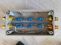
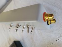
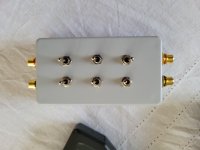
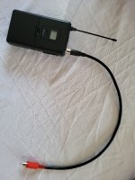
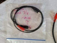
I made one channel at the moment to test it. I used switches to sort one by one withe the following values 10k to the channel and 47Ω + 47Ω + 220Ω + 600Ω. So to achieve several levels of attenuation. The first question is do I leave the 10k untouched and the second is can I use pots in both places?

I made one channel at the moment to test it. I used switches to sort one by one withe the following values 10k to the channel and 47Ω + 47Ω + 220Ω + 600Ω. So to achieve several levels of attenuation. The first question is do I leave the 10k untouched and the second is can I use pots in both places?
Attachments
-
 20221211_105400.jpg350.4 KB · Views: 66
 -
 20221211_105355.jpg290 KB · Views: 62
 -
 20221211_105349.jpg281 KB · Views: 55
 -
 20221211_105319.jpg263.9 KB · Views: 70
 -
 20221211_105324.jpg399 KB · Views: 63
 -
 20221211_105312.jpg607.1 KB · Views: 56
 -
 20221211_105246.jpg539.9 KB · Views: 59
 -
 20221211_105451.jpg460.7 KB · Views: 67
Thank you. Now we have the prototype let's make it better. Any suggestions? Should I have a capacitor at input for DC blocking? What about adding pots instead of resistors? Should I increase the main 10k resistor to a bigger one? Thanks
As mentioned, i don't think pots would be benneficial being that your source will almost always have some pot or fader in the chain (pots adds more potential flaws than simple resistors, u ll hardly have to change a resistor because it failed rather than the circuitry, but a cheap carbon pot... ) . About the capacitor, u could put it to be extra safe, but odds are, there is an output or an input capacitor in the mixer or the receiver. The value is easy to calculate to have the desired low rolloff, yet again, i would skip it. Think it this way: if the source is putting DC and its load doesnt have an input decouplig cap, if you were not putting ur attenuator into the equation, the DC would be there. So its not that u are adding chances of DC with your jig. In this regard putting a cap would be like thinking u need to put a cap in series with the cable in case something odd happens without ur jig. I would only think to put a cap if u were to actively sum the signals with an op-amp in case it fails.
If i got it right, your 10K resistor is in series with the others, which assures u the desired impedance the rec out sees. U seem to have many resistor combination values already. I would meassure the attenuation with a simple voltmeter before thinking of improving it. I don't think much can be done here if the attenuation was achieved.
Best regards!
- Home
- Design & Build
- Construction Tips
- L pad to attenuate line out to mic in or something else