Greets!
No, not really beyond he apparently continues to 'streamline' his math like programmers have done to T/S box calculators, with the consequent reduction in accuracy. In the scheme of things, these differences mean nothing to folks who don't measure drivers, their room, speakers, and the speakers in-room since they have no way to correlate what they're hearing to the sim. Factor in that down low our hearing acuity sucks and even what looks like gross differences below ~150 Hz in a sim would be hard to detect in an in-room A/B comparison.
Still, when 'bench racing' sims, it would be nice for everyone to be using the same 'rules' and that they ~mirror any properly done nearfield measurements.
BTW, I use to have real problems with getting consistant results (i.e. what I expected to see) regardless of which WS I used, even after a computer upgrade to Win XP pro/MC 2001 pro, until I started (re) calculating them by clicking on 'math/calculate worksheet'. For whatever reason neither 'refresh' nor 'ctl R' has worked at all in either the demo 8 or licensed program and after several recalculations, scrolling down to update the various plots quits working correctly on the one we look at most, the 'far field' plot.
Anyway, using whatever version of the PORTED WS I have (downloaded 2-6-04), once I reduce the stuffing to 0.2 lbs/ft^3 with none below position 'L01' I get a 'close enough' looking sim to yours once the difference between the PORTED and ML-TQWT vent orientation is accounted for.
GM
Bingo. Yeah. I've just had an email from Martin -I'd asked him to take a look, and that was his observation, so we're in the clear after all, albeit with a slightly 'off' stuffing level.
Cheers
Scott
Cheers
Scott
Thanks Scott and GM. Great input for someone new at this game!
Interestingly, I ran across another thread:
http://www.diyaudio.com/forums/showthread.php?s=&threadid=42409
where Martin and GM did some sims for Coral Flat 8s. It appeared that an ML-TQWT might be suitable for the Flat 8s, and it looks as though the T/S's for 8s are not that very different from those for the 6s.
Scott, you mentioned that the ML-TQWT design could be fixed using a 2-ohm resistor and varying the ML. Were the figures you posted based on GMs quick-tapering design? Alternatively, any chance of optimizing the ML-TQWT and re-posting the design (since you have the newer worksheets, and are so much better at it). I'd like to go with a ML-TQWT if possible, since the Coral's are old, and I may have to replace them at some stage.
Thanks again to both of you (and Martin, of course).
No, they were for the same straight, untapered MLTL I came up with before (Martin's ML TQWT sheet can model straight, as well as tapered enclosures you see). The only updated sheet I currently have is the Ported Box sheet which can't model tapered enclosures, so I'm using the current sheet for those, same as GM's using.
As you clearly like the tall ML TQWT enclosure (and why not?), I've played around with some dimensions a bit more. GM's fast tapering job looks like it provides the best response for the Corals of this particular tapered geometary with 2 ohms series resistance applied. However, if you're willing to increase that a bit to around 4 ohms, which isn't out of sight (I've used 10 ohms before now and as resistors are cheap, you can afford to experiement a bit!) then Martin's original ML TQWT enclosure, ironically, will also work quite well: http://www.quarter-wave.com/Project02/FE-164_ML_TQWT_Design.pdf
You'd just need to increase the port radius to 2" up from the original 1.5" Response rises somewhat, but the series resistance will sort that, and you need to remember the boost room-gain will provide -the room is the major factor low down, with box speakers at any rate. Frequency response of that enclosure is below. GMs generally looks similar, just a bit flatter.
Best
Scott
Attachments
Great!
I just plugged in GM's numbers (minus the 2 ohm resistor, I couldn't figure how to do that, I guess I'll have to hit the books some more), and managed to duplicate something along the lines of what you had posted... Good so far, and then Macdemo crashed...!!
Following your lead has got me up to speed much faster; and GM's tip about refreshing via Math/Calculate worksheet helped, I think I was chasing my tail for awhile.
Thanks again to all.
I finished building my voigt pipes on friday. I used Scott's port design.
Drivers are FE207E, cabinet is LCON dimensions (except for port), damping applied as suggested except 'bumpy' foam used directly behing driver to soak up driver reflections.
One point to note: I couldn't find 3" pipe locally for the port, so I designed a rectangular port with the same cross-sectional area and length as Scott's suggestion. This is still centred 4" up from the bottom of the baffle.
Coming from my previous speakers (modded Loth-X BS1) these things are already like a breath of fresh air. The loth's are very good at what they do, but clearly offer a very narrow window onto the performance. Both HF and LF are curtailed compared to the voigt's, which also have a cleaner mid.
I have assembled the drivers as described above, but not yet played around with stuffing etc. I don't see any point in tweaking until drivers etc. settle down.
Having said that, I did assemble both a LR (1.5uH/8ohm l-pad) filter (parallel in series with the driver) and a RC (16.4ohm/3.0uF) (series in parallel with driver) filter.
I have plugged both of these networks in to give me some smoothing of the driver while it runs in. Once everything settles down I will try alternative options.
The amp is a recased and highly modded t-amp. So far I cannot fault these £200 speakers! The bass is focussed and even, despite my large living room. Imaging is holographic and transparency rivals my old Magnaplanar MG.5QR.
Thanks a lot Scott. Fully recommended design!
(photo's to follow...)
Another coincidence. I'm just modding a Class-T myself to use with these ML-TQWT's, so it's good to hear that the combination works.
Hi!
I have an ML TL with Fostex FE206 E (MJK's project 5).
It sounded a bit "hot " at first. Adding some series resistance helped a bit, but at a cost of reduced efficiency.
Then, just as an experiment, I tried something else: I connected the secondary of an 220v /12 v 50W mains transformer in series with the speaker. At the primary side (200v) I connected a 20K pot.
Well, this tweak made Fostex sound much more pleasant. Don't ask me why, try it! 😎
regards,
Vix
Scottmoose said:No, they were for the same straight, untapered MLTL I came up with before (Martin's ML TQWT sheet can model straight, as well as tapered enclosures you see). The only updated sheet I currently have is the Ported Box sheet which can't model tapered enclosures, so I'm using the current sheet for those, same as GM's using.
Greets!
Huh?! You're saying you can't load SO (top) and SL (bottom) separately with different areas into the new WS?
GM
talatnat said:I just plugged in GM's numbers (minus the 2 ohm resistor, I couldn't figure how to do that, I guess I'll have to hit the books some more.........
Thanks again to all.
Greets!
You're welcome!
Unless I'm missing an obvious 'trick', changing the WSs each time you opened them would be more trouble than it's worth since you can't save them in the demo, so make a little spreadsheet to calc the new T/S parameters to load into the WSs:
Qed' = Qed*(1+Rs/Re), where Rs is the series resistance and Re is the driver's DC resistance.
The WS will auto recalc Qtd.
Qmd, Vas, Lvc is unchanged.
Re becomes Re+Rs.
BL changes only fractionally, so not enough to be worth the effort to recalc.
If you want to know the new, lower efficiency rating without doing a sim:
n0 = 9.6352*10^-10*Fs^3*Vas(liters)/Qes'
SPL = 112.018+10*Log(n0)
GM
Good question. I've just put some examples up for all of 5 minutes, but I've wiped them temporarily as it might not be quite fair if it's a bug -this is still a test sheet afer all. I'll ask Martin about that one and get back to you. Suffice to say at the moment however, in my experience, it throws a fit if you try to model a tapered enclosure.
Regarding the latter -that's a really useful tip that I'll use myself until I get a full, decent version of MathCad. Thanks!
Cheers
Scott
Regarding the latter -that's a really useful tip that I'll use myself until I get a full, decent version of MathCad. Thanks!
Cheers
Scott
OK, I've found out what it was. The new sheet can indeed model tapered enclosures (I checked with Martin to be sure), but it was being thrown out when I ran it by a modified ham radio program running in the background (I'd borrowed a PC from my Dad temporarily). I've run a few checks with different drivers and cabinets on my own system now, and they match to the current sheet almost perfectly.
Problem solved. Thought it was a bit odd!
Cheers
Scott
Problem solved. Thought it was a bit odd!
Cheers
Scott
Scott, that's good to know.
After a few crashes, I figured Macdemo to be a resource hog, and now shut down as many other applications I can live without, and then run it. Seems to behave just fine now.
As an aside, in playing around with the designs that you and GM came up with, it seems that a very low So (~0.1 Sd) and a large Sl (~10) yields a somewhat flatter curve. Elsewhere, Bob Brines has suggested (after suitable qualifications) using the "shortest, fattest" pipe to meet the bass cut-off goal, and the "smallest diameter, shortest port" to meet both the bass-cutoff goal and reduce unwanted higher harmonics. I've also read that a low So isn't recommended, and that one shouldn't stuff beyond 0.25 lb/ft3, and so on.
I was wondering whether someone had put together any rules-of-thumb of what works better in actual practice. For example, is it better (or acceptable) to use a somewhat rougher FR vs. shooting for a truly flat FR if criteria X, Y and Z are met. This doesn't detract from the value of doing the sims, but I'm curious whether the collective wisdom of those who have actually built ML-TQWT's enables them to recommend some design constraints under which to optimize the sims.
I guess the reason I'm asking is that the more I read up on this, the more I realize how little I know! Thanks in advance for any suggestions...
A small addendum
There are some good pointers in the article:
http://www.t-linespeakers.org/design/MJK-for-dummies/index.html
But I am shooting more for the sort of suggestions that brought about this thread on the FR of the LCON pipe, and again why some prefer it to a flatter FR. In other words, what are the tradeoffs one should keep in mind?
Why do some like the original? Personal taste I suspect more than anything. Fair play -they're the one's listening to it, and they have to like the sound!
Efficiency is the primary one I suspect. Take horns for example. 99% have a terrible measured and / or predicted response -don't they? Well, yes. And no. It depends on the criteria you have. Some people value efficiency above everything else. They love the scale, the sense of immediacy, the subjective dynamics (note: no rear loaded enclosure can improve the dynamics of a driver, but the combination of other factors makes it sound like that) that horns provide, and could care less if the frequency response is rough, or the bass response is weak. However, for me, 20db holes in the response is starting to get beyond 'reasonable' levels. GM has pointed out that our hearing acuity drops with frequency, so you can get away with having a fairly rough response in the lower registers without noticing, particularly since as our hearing is amplitude based, and we'll key off the peaks. I'm not sure I'd risk that much over 100Hz though.
I'd modelled these enclosures a few months back and found them on my hard disk when I was cleaning it out, and thought I'd put them up as they might be of some use to someone. The mod I suggested will give a much flatter response, and deeper bass, at the expense of reduced efficiency. 91db is pretty good though in my book: 1w will be fine for ordinary listening.
A few general ML TQWT ideas. This is not the only way, but some find it a good starting point. Firstly, I'll note that it depends on the driver you're using. I try not to aim for a specific cut-off, at least not initially, but concentrate on trying to get the flattest response possible. Note that what is flat in anechoic terms will not be in-room, but it's a good place to start.
I wouldn't bother with a line-length of more than 60". Longer lines will likely give deeper bass, but there are other ways of achieving that.
So. This is a tricky one. Nomally, I would say don't go for an area less than Sd. However, if your choisen driver has a Qts of less than 0.3, and after you've tried everything else the system looks like it needs some more gain, try reducing this a bit, down to 0.5Sd, and adjust in increments.
Sm. Minimum area 3Sd. Maximum area 7Sd. Don't try going for more than that, you'll just run into issues such as a sag around 100Hz etc. Now, be wary. Say you're using an FE207E 8" full range driver. That's got an Sd of 31"^2, give or take. So 7Sd will give the base a surface area of 217"^2. Say your cabinet is 10" deep, that would mean that the width at the base would be a monstrous 21.7". So you need to keep the physical dimensions in mind; you could hit upon a magnificent response, but if it's not going to fit in your room, it's not going to be of much use to you!
Start with a driver position at 0.5 the line-length and if there is a spikes or dip at around 100Hz-200Hz, try moving it up and down slightly to flatten that out. 0.5 is a good general compromise and starting point though. Stick with 0.25lbs ft^3 of stuffing initially. if it needs more, don't go beyond 0.5lbs ft^3. If it needs more, the cabinet dimensions will want a re-think.
Ports. Start with a small, 1" radius port as short as possible, and increase the length in increments to try to flatten the response out, up to, say, 6" in length. Keep it close to the bottom: 3" from the base is a good starting point. If you get no joy, increase the port radius to, say, 1.5", reduce the length to the shortest possible and repeat this. Then again for a 2" radius port. Only ever change 1 variable at a time so you know which has affected the response.
OK, say you've got a good combination, but you want more bass, the driver can go lower (don't generally try to go more than 10Hz, maximum, lower than the driver Fs and preferably not that much), and you have the room. OK, increase the area of Sm, and adjust the port dimensions, if necessary, to flatten the response.
As I say, this is a long proceedure, and there are other ways, probably better too, but it works and it gets you used to using the worksheets and seeing how the different variables affect the response.
Talatnat, Scottmoose; I am still following this thread😉 I hope you come up with a pretty good enclosure for the Corals for sure😉 I dont understand half of the acronym's you use, but just hope a nice box will be the result of these discussions🙂 I cant contribute with a lot, sorry😉 But I will be happy if you post a nice box for those Corals🙂 I sure would like to hear them baby's sing at their best😉
Steen😎
Steen😎
Steen: OK, I'll keep you posted as things progress.
As of now, Scott and GM each came up with a design that look very close to best-of-breed for that particular configuration. Scott's is a ML-TL, a 42-in.-high tower, and GM did a 72-in. ML-TQWT, which is a tapered triangular box. Both reach low frequencies of around 45 Hz, unaided by room effects.
If you are looking for detailed projects, you can use MJK's step-by-step accounts at http://www.quarter-wave.com/Project03/Project03.html , which is similar to Scotts design, and http://www.quarter-wave.com/Project02/Project02.html , which can be substituted for GM's design. These two projects will give you a good basis for what Scott and GM recommend.
At the moment, I've gone back to scratch and am planning to break in my speakers (awaiting the the class-T amp, which is almost done), and to then measure the T/S parameters to see if either of these designs need any tweaking. I am somewhat uncomfortable using Coral's published T/S params, or the ones given to me that I listed earlier, since the speakers are 20-25 years old, and I'm unsure of their condition. Also, this is an excuse for me to learn how to do everything from the basics...
I'll post as I learn more about the Coral drivers themselves.
A safe bet for Coral 6's? Dalines?
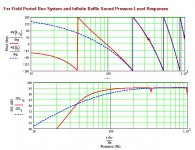
Just for kicks -- I realized I should have done it earlier -- I did a sim of Coral Audio's recommended bass-reflex box using the ported-box WS and GM's params. Even unstuffed (and minus 2-ohm series resistor), it looks like a surprisingly clean FR curve, decent LF, with just a couple of sharp dips (standing waves?). FR curve attached below.
The Coral dimensions: 10-4/5 (W), 20.5 in. (H), 7-2/3 in. (D)
The driver is mounted in a 7-in-dia baffle opening located 5-9/10 in. from the top. The port is located 4 in. from the bottom, and is a square of 2-3/5 x 2-3/5 in., and 4-in long. GM's params: Fs = 68 Hz
Re = 8 ohms, Lvc = 0, BL = 9.46 NA (calc'd), Sd = 214.0834 cm^2 (6.5" nom.), Rs = 2 ohms, Vas = 31.346 L, Qed = 0.433, Qmd = 5.671, Qtd = 0.494 (auto calc includes Rs).
Dimensionally, it's about the same as Scott's design (So, Sm = 90 in.^2), and about half as high (20.5 vs 42 in.).
As a start, would it be prudent (for a neophyte) to just build the Coral box, since it seems to provide decent LF response, especially if will be used in a small (bassy) 13x13 ft room?
And, this is just curiosity (and DIY fun): Next, once things settle down, would it be possible to couple the Coral box to a daline-type TL? There were a couple of threads re: dalines a few years ago, but nothing conclusive. GM outlined a personal system for such daline-type designs, noting that they require low Qt/Fs drivers (not exactly Coral's strengths). Some mentioned splitting the volume to 1/3rd box, 2/3rd TL. And, interestingly, MJK mentioned that he did not seem to have much success modelling the dalines with the Mathcad WSs.
Questions:
1. I was just thinking that if the daline experiment didn't work, I'd still be left with a pair of decent Coral boxes. Is this feasible, or would the basic Coral box just not work for a daline?
2. Will using a rear-firing port for the Coral boxes to accommodate (aesthetically) the daline TL be a mistake?
3. Can just modifying the length of the daline TL pipe enable one to tune the LF output to suit a room, or is this just my pipedream?
I'd appreciate any suggestions and advice.
Attachments
Re: A safe bet for Coral 6's? Dalines?
Greets!
MathCad isn't currently working for me, but in theory, 19.30" x 11.93" x 7.37" with the driver down 8.93" and the vent near/at the bottom will be even smoother, though probably not audibly so, especially once a little damping is used. Anyway, the notches are the vent comb filtering with the driver's output, so easily damped.
Whether to build them or not is up to you. It's simmed response assumes it will be ~up against a large wall at ~ear height, making it much more rolled off perched on stands well away from any, so it boils down to how much efficiency you're willing to trade for a ~flat in-room response.
Yes, you can convert it to a Daline tuned to ~48 Hz, though all things considered, bottom firing seems the best option. Typically, damping the vent exits is the way to fine tune them to the room, just like a TL.
GM
- Status
- Not open for further replies.
- Home
- Loudspeakers
- Full Range
- L C of Norway Voigt Pipe -quick fix