I am about to make a board (Eagle) for my KC7 implemantation....
What will be the "best" choice of:
-ground plane on component side
-ground plane on back-side
-both.....??
I am also implementing a 74HC125 logic to be able to drive the output when the board is placed close to the DAC, and the clock is feed backwards via 50ohm coax.
Should this logic, and corresponding transistor (2N4401) have it's own +5V supply, or could I just use +5V from the clock ???????
Lyra
Lyra said:I am about to make a board (Eagle) for my KC7 implemantation....
What will be the "best" choice of:
-ground plane on component side
-ground plane on back-side
-both.....??
I am also implementing a 74HC125 logic to be able to drive the output when the board is placed close to the DAC, and the clock is feed backwards via 50ohm coax.
Should this logic, and corresponding transistor (2N4401) have it's own +5V supply, or could I just use +5V from the clock ???????
Lyra
Hi
You may look here for layout suggestions
http://members.chello.nl/~m.heijligers/DAChtml/Supply_decoupling.pdf
regards
The Art of PCB Layout Design
Hi Lyra,
First remember electrons don't take sharp corners so avoid this situation by making rounded tracks.
http://www.audiotuning.de
(Click on Precision Clock)
To get the ground noise to an absolute minimum use a ground plane. See also:
http://www.national.com/rap/Story/0,1562,18,00.html
To quote from Audiocom:
The basic platform of Superclock II is its printed circuit board. This is formed as an extremely low impedance ground plane over which the components are placed. Very low impedance ground planes contribute to signal quality and are essential when handling radio frequency signals which are of exceptionally low distortion and phase jitter. The ground plane shields the radio circuits from the invisible capacitor formed when the board is mounted close to metalwork
Link:
http://www.1st-4-audio.com/control/news/anmviewer.asp?a=105&z=15
Even better go for a 4-layer board:
http://www.lcaudio.dk/com/intlcl.htm
Carbon composition resistors have the lowest inductance and should be used, preferentially in SMD format.
Also note that even a short trace on the PCB has inductance. So keep traces as short as possible, preferentially below one inch.
As for the power supply I quote from
http://www.trichordresearch.com/cdupgrades.html
Independent Power Supply available to isolate clock frequency noise from the rest of your CD player and also reduce other digital noise from the player entering the clock circuit.
Please see also:
http://www.net-audio.co.uk/clockpsu.html
Most authoritative paper:
http://www.analog.com/Analog_Root/static/pdf/dataConverters/MixedSignal_Sect10.pdf
(Page 17 and further)
Lyra I hope this answers your questions.
😎 😎
This entire post has been spell checked by Word in Windows.
Re: The Art of PCB Layout Design
dear all,
At the freqs the round edgess are nonsense (if you know how the currents run and which parameters affect the routing of the current).
The impedance of the groundplane is not well understood by many designers, including the Audiocom guys (see above, and realise that currents run in loops).
A 4 layer board may be needed if the clock signal runs at bigger distances, like in our DAC design. I see no reason in a clock circuit, 2 layers are enough, at least that is what my measurements indicate.
Bottom line:
Control the currents through the groundplane, by making sure they travel through the shortest portion (i.e. place decoupling cap closest to the gnd pin of a chip)
Reduce RF currents by placing series impedances in supply and clock / data lines
Organise the floorplan in a logical way so the higheste frequencies / currents travel shortest way
NEVER interrupt the groundplane
By doing so, we achieved a virtual equipotential groundplane, now connect / decouple all component references (including their ground connections) to ground
succes
Elso Kwak said:Hi Lyra,
First remember electrons don't take sharp corners so avoid this situation by making rounded tracks.
http://www.audiotuning.de/english/index.html
(Click on Precision Clock)
To get the ground noise to an absolute minimum use a ground plane. See also:
http://www.national.com/rap/Story/0,1562,18,00.html
To quote from Audiocom:
The basic platform of Superclock II is its printed circuit board. This is formed as an extremely low impedance ground plane over which the components are placed. Very low impedance ground planes contribute to signal quality and are essential when handling radio frequency signals which are of exceptionally low distortion and phase jitter. The ground plane shields the radio circuits from the invisible capacitor formed when the board is mounted close to metalwork
Link:
http://www.1st-4-audio.com/control/news/anmviewer.asp?a=105&z=15
Even better go for a 4-layer board:
http://www.lcaudio.dk/com/intlcl.htm
Carbon composition resistors have the lowest inductance and should be used, preferentially in SMD format.
Also note that even a short trace on the PCB has inductance. So keep traces as short as possible, preferentially below one inch.
As for the power supply I quote from
http://www.trichordresearch.com/cdupgrades.html
Independent Power Supply available to isolate clock frequency noise from the rest of your CD player and also reduce other digital noise from the player entering the clock circuit.
Please see also:
http://www.net-audio.co.uk/clockpsu.html
Most authoritative paper:
http://www.analog.com/Analog_Root/static/pdf/dataConverters/MixedSignal_Sect10.pdf
(Page 17 and further)
Lyra I hope this answers your questions.
😎 😎
This entire post has been spell checked by Word in Windows.
dear all,
At the freqs the round edgess are nonsense (if you know how the currents run and which parameters affect the routing of the current).
The impedance of the groundplane is not well understood by many designers, including the Audiocom guys (see above, and realise that currents run in loops).
A 4 layer board may be needed if the clock signal runs at bigger distances, like in our DAC design. I see no reason in a clock circuit, 2 layers are enough, at least that is what my measurements indicate.
Bottom line:
Control the currents through the groundplane, by making sure they travel through the shortest portion (i.e. place decoupling cap closest to the gnd pin of a chip)
Reduce RF currents by placing series impedances in supply and clock / data lines
Organise the floorplan in a logical way so the higheste frequencies / currents travel shortest way
NEVER interrupt the groundplane
By doing so, we achieved a virtual equipotential groundplane, now connect / decouple all component references (including their ground connections) to ground
succes
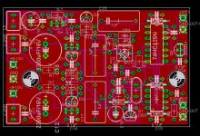
The layout seems pretty OK to me but two things:
1 those 1 uF, why don't choose small 1 uF/63 V polyester? Maybe you chould go for 10-100 nF + 10 uF?
2 The 74HC IC hasn't got a decoupling cap close to pin Vcc.
Maybe you should consider SMD because this is better in almost all resepcts and it's not particulary hard to solder. Go for 0805 parts and SOT23 transistors.
Lyra said:This is my PCB-design as for now.
There might be some faults here and there. Keep in mind that this is my first layout using Eagle.....
BTW: the size of the board is aprox. 50x80 mm.
If there are something that look's not OK, please shout out
Lyra
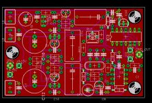
Hi Lyra
one remarks, as my response is limitted as I do not have the schematic at hand
You place the ferrite bead closer to the chips than the decoupling caps. I'd suggest to swop these, the cap should realy be close to the chips
succes
When it comes to traces, always make them as short as possible, cut the corners also. Avoid 90 deg angles. Still I think you really should test SMD because smallness is very positive when it comes to digital circuits and oscillators. Not everything have to be SMD but resistors, < 100nF caps, transistors (regulators), IC's. The crystal can be holemounted.
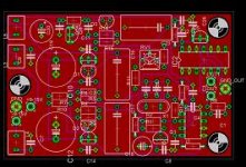
Mask the groundplane in the skrew holes so the screw and/or the distance not make contact with the groundplane.
Look at the picture below.
Mask the groundplane in the skrew holes so the screw and/or the distance not make contact with the groundplane.
Look at the picture below.
An externally hosted image should be here but it was not working when we last tested it.
74HC125
Hi, See post #1 where this is explained. (74HC125).
promitheus said:What does the IC2 do?
I know that the Kwak Clock has only one IC on it.
Hi, See post #1 where this is explained. (74HC125).
Duhhh....
Thanks.
Is there a layout for the clock? Does anybody have a PCB?
Elso I have a question.
I use my CD player as a transport. I feed the DAC with Optical Toslink. This goes into a CS8420 Receiver upsampler. This is where the Master clock is. After that the digital signal goes through a DF1704 and to the dacs PCM1704 but these have no clock. They are clocked from the signal.
The Mainboard is from the magazine Elektor Electronics and they have an option on the board for an external clock.
My question. Is it enough to use the Elso Kwak clock as master clock here? Or should I do something more?
promitheus said:did you ever finish the clock on this pcb?
No.......
promitheus said:Is there a layout for the clock? Does anybody have a PCB?
This board was newer finished
 ....sorry, but new job, moving to another appartment, and not too much time left....
Maybe I pick it up a little later.........
I don't have a PCB, an have never get it 100% verified that this sollution really works as intended. If I don't remember wrong, there was something I wished I had done differently, but I am not sure what it was.
Think I can find the Eagle-files if someone are interested....
...Just maybe I make a simpler layout (single-sided board) and nothing extra, for placement inside one of my players in a little while.....some weeks!?
- Status
- Not open for further replies.
- Home
- Source & Line
- Digital Source
- Kwak Clock layout ???