I found this over in the SS forum, around a half dozen threads related to it. In one thread it was suggested that this was an old tube circuit, but they never produced any evidence of that. Anyway, it provides around a 100X improvement in distortion over a single device. Only uses two devices. (Looks similar to a Darlington) Works with all N type devices, including tubes. It uses feedforward error correction rather than feedback. And it functions as a V to I converter, but is suitable for driving a cascode above it for V to V use. Still trying to get a clear picture in my mind how it works so well, but supposedly the second device is adding opposite distortion of the first device, so cancelling. Zo = R3+R4. Gain == R4/R2 (for Rload >> R3+R4)
R3 has to be critically adjusted for linearity. For gain of 3 in post #27 circuit: R1 100 Ohm, R2 332 Ohm, R3 318 Ohm, R4 1000 Ohm. More info and a diagram in the link:
http://www.diyaudio.com/forums/solid-state/74861-single-darlington-line-preamp-3.html#post856982
R3 has to be critically adjusted for linearity. For gain of 3 in post #27 circuit: R1 100 Ohm, R2 332 Ohm, R3 318 Ohm, R4 1000 Ohm. More info and a diagram in the link:
http://www.diyaudio.com/forums/solid-state/74861-single-darlington-line-preamp-3.html#post856982
Last edited:
Interesting circuit. I didn't read the article, but part of the operation will be the gm of VT1 being boosted by having a greater current due to R1. I discussed this phenomenon for the complementary pair in Wireless World about 10 years ago. This alone will reduce the distortion, without the feedforward of R3.
It might assume a BJT exponential characteristic; if so would require a remote-cutoff valve!
It might assume a BJT exponential characteristic; if so would require a remote-cutoff valve!
Last edited:
I pulled the diagram over for easier reference (attachment)
My present thinking on this circuit is that a normal follower circuit would be non distorting if it weren't for the non-linear base to emitter (or grid to cathode V for tubes) voltage drop(s) appearing in series with R2. Otherwise the current thru R2 would be Vin/R2 exactly. (the collector current being a close copy of course) With R1 present, Q1 senses the additional base to emitter error Voltage at Q2's emitter, and so draws additional current to correct that. Which I'm guessing is what DF96 was getting on about. Seems like Q2 collector and R3 act like a bootstrapped CCS load for Q1 then. Not sure how R3's value is so critical for nulling the distortion though.
Edit: Maybe Q1 collector current is overcorrected somewhat, so R3 has to be tuned to add in just the right amount of under-correction from Q2's colllector?
It would seem that this scheme could be extended even further by adding on a Q3 follower, with say a 10 Ohm R1' between it's base and emitter and R2 moved on down to Q3's emitter (with a lowered value). Basically the whole thing now looking like a Darlington triple, with a final emitter resistor R2 to ground. Then Q1 collector current would be overcorrected, Q2 would be perfectly corrected, and Q3 would be under corrected. Tying all the Q1,2,3 collectors together somehow with some linear resistor network should allow a perfect distortion null (hopefully). Or maybe Q3 collector just provides the bootstrapped load drive thru R3, and Q2 collector provides the perfect output. Just rolling some tubes and resistors around in my head, you get the idea.
Attachments

Last edited:
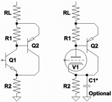
Triodlington no mystery: R1 holds triode cathode at near constant current...
1/(Mu-1) feedback from plate to cathode Schades Q2 BJT toward linearity.
Have no idea why an all sand version claims better linearity than Darlington?
Q1 at constant current due to influence of R1 makes for a big do-nothing...
1/(Mu-1) feedback from plate to cathode Schades Q2 BJT toward linearity.
Have no idea why an all sand version claims better linearity than Darlington?
Q1 at constant current due to influence of R1 makes for a big do-nothing...
It is important that Q1 has nearly constant current, as that avoids distortion due to Q1 Vbe changing with signal. In a conventional Darlington (without R1) you get the same Vbe change in both transistors, so distortion is potentially twice that of a simple emitter-follower. This circuit does two things: R1 greatly reduces the Vbe change in Q1, while R3 compensates for the Vbe change in Q2 (and Q1 too). That is why R3 value is critical - it is like balancing a bridge circuit. It may be that slightly different values of R3 can cancel either 2nd-order or 3rd-order distortion, as Q1 distortion will not be exactly the same as Q2 distortion. The downside of this circuit is that it will have a slightly higher output impedance so could get more distortion in the next stage.
It probably won't work quite as well with valves because their gm does not depend quite so drastically on current flow as a BJT, and the gm vs. current ratio is not fixed as it is for a BJT. Cancelling Q2 distortion will still work, but the extra correction for Q1 distortion will be more approximate for valves.
It probably won't work quite as well with valves because their gm does not depend quite so drastically on current flow as a BJT, and the gm vs. current ratio is not fixed as it is for a BJT. Cancelling Q2 distortion will still work, but the extra correction for Q1 distortion will be more approximate for valves.
Well, constant current in the emitter of Q1 does not linearize anything
when it is in series with the voltage drop across emitter of Q2, which
is NOT at constant current and varies considerably.
This can work, but you have to hide the non-linear emitter from the
decision making process. Above the collector or plate it will have far
less disruptive influence.
--------
Note: Only the TrioSiziklai pair knows plate Voltage and can use the
optional bypass capacitor. Our BJT Sziklai pair knows only of current
and must rely entirely upon R2 for feedback.
In both cases: R1 is held at constant current, and Q2 dumps the
larger current swings, so the decision maker won't see them...
--------
Untill I understand the theory of operation better, I have no faith in
the Darlington feedforward arrangement. It makes no sense to me...
Attachments
Last edited:
Ahhh!! "Bridge circuit" so thats the key, I see more now. Looking at the original values in the diagram (post #3 above), R4 = R2. (and R1 approx. = R3) So the voltage on R2 is (Vin - Vbe1-Vbe2). So current thru R2 (and the nearly same current thru R4) is (Vin - Vbe1-Vbe2)/R2. R1 current is Vbe2/100, So Vbe1 is held close to constant. Since Vr2 is off by about Vbe2, so is Vr4 (from B+). R3, with Q1 current thru it, drops the extra Vbe2 to correct Vr4. Output at Q1 collector.
Last edited:
Constant current in the emitter of Q1 avoids the distortion of Q1 Vbe, so this is an immediate improvement over the plain Darlington - we have halved the distortion. Then R3 adds a feedforward correction for Q2 Vbe. R1 thus has two roles in the circuit: it increases the current in Q1 so the percentage change due to signal is smaller, and it senses the Vbe of Q2.
There are minor corrections to add, which is why R3 is not exactly equal to R1 (or R1 x R4/R2 if we want gain). The corrections include Q2 base current, and Q1 Vbe changes. To a first approximation Q2 base current requires a slightly smaller R3, and Q1 Vbe changes require a slightly bigger R3, so R3 ends up roughly where we started.
The input to the circuit is Q2 Vbe + V R2, the output from the circuit is V R3 + V R4. Assuming unity gain and infinite beta for simplicity, R4=R2, and V R3 = Q2 Vbe so output = input. The only difficult bit is working out the minor corrections to R3 to get the last bit of distortion cancellation.
Like DF96 said! Couldn't say it better myself. Thank you so much for the explanation.
The gm proportional to current appears to make this scheme fit well with bipolar devices, allowing Q1 to emulate Q2 for corrections. If we were to consider gm proportional to voltage (square law Mosfets, power tubes with grid island effects), I wonder if this can also work similarly or with some simple mods. At least some of the small corrections for Q2 base current and finite Q1 Beta would go away.
The controlled output Z here also brings to mind the use of this circuit as a driver stage for a Schaded feedback output stage. (a constant feedback voltage divider)
Then I wonder how this could be fitted with a cascode stage above it for higher gains. Apparently the original Mikhail Kulish article gives such a circuit. But its in Russian. I will try to decipher the diagrams.
I suppose one can just attach the cascode's cathode or source/emitter to Out2 since R3 and Q2 are supplying currents to it. But if Out2 is frozen voltage wise, maybe R3 won't be supplying the correct current. In which case maybe Q2's collector should be controlling the cascode's grid/gate/base. Or, visa-versa, Q2 collector driving the cascode cathode/source/emitter and Q1 coll./R3 somehow driving the cascode grid/gate/base.
Last edited:
The main distortion cancellation of Q2 Vbe does not make any assumptions about Q2 transfer function, so would work for any device. The minor corrections would need adjustment, so the total effect might not be quite as good.
The main problem with valves is that they require negative bias. This complicates things, as AC and DC paths need to be separated. Extra bypassed cathode resistors or LEDs may be needed.
Adding a cascode is possible. Get rid of R3 and R4, and just parallel the collectors to drive the top device emitter/cathode. However, you also now need R1=R2, so the main gain and the feedforward gain are equal. This may limit the design.
Yes. The circuit is looking attractive in certain ways. Maybe if Q2 were a Mosfet and Q1 a tube, negative bias issues could be minimised. But I think the minor corrections may want Q2 and Q1 to have similar non-linearities. Might still work out OK with some resistor tweeking.
On the cascode, if R1 = R2 would this not require R3 to = R4 approx? Seems like you cannot just delete R3 then. Alternately, trying to make R3 and R1 go to zero would fix the output connection, but would kill the error correction. How about leaving R3 in, but delete R4 and take the output to the cascode from Q1 collector? Hmmm, R3 doesn't do anything then. And my idea of using the cascode gate/grid isn't working either due to the inversion there. Confused here.
Edit for cascoding:
How about R4 B+ end connects to the cascode grid/gate at B+, then Q1 collector connects to the cascode cathode/source, and R3 still connects in between Q1 and Q2 collectors? Ehhh, still freezes the Q1 collector. Back to the drawing board.
Another issue would be whether a triode or triodes could be used in this Kulish scheme. Seems that the Rp's would be mostly tracking, so the gm's could be seen as just proportionately reduced if the Mu's match maybe, but details count here for tiny distortion effects.
Last edited:
For cascode no need for R3 and R4 - all they do is convert current to voltage. That now happens at the upper device. You just have to make R1=R2 to match the gains. Minor adjustment might offset Q1 distortion, but probably not exactly.
You could make R1=R2 anyway, but that constrains the design so for normal voltage output better to have more freedom.
You could make R1=R2 anyway, but that constrains the design so for normal voltage output better to have more freedom.
I guess one would have to tweek R1 then, instead of R3, to get the distortion nulled? I was thinking earlier of the voltage drop induced on R4 by Q1's current, in addition to the R3 drop, but I guess that is insignificant compared to Q2's current. So only a tiny re-adjustment effect required then (R1 tuning presumably) from deleting the resistors (R3,R4).
Maybe altering the gm of Q1, say double or triple that of Q2, could provide some design headroom for R1 value too.
Do you think this scheme would work usefully for triodes (Q1,Q2) with their Rp effects? Or not worth bothering with triodes due to the small residual gm left, after Rp feedback get's figured in.
Edit: For the voltage output case. I guess triodes would work fine for the cascode case.
Edit: It just occured to me that some interesting effects could develop for the triode case (voltage output case) if the design gain were matched to a tube Mu (Q1). Constant current. I guess the Mu would have to match output gain to input plus the R1 signal. But then again, the R1 signal is a current. So maybe the Mu has to be mismatched some (versus stage gain) to counter the R1 current input. There has to be some kind of grid resistor on Q2 also to convert current to drive V for Q2. Guess the Q1 current can't stay constant. Hmmm....
Last edited:
- Status
- Not open for further replies.
- Home
- Amplifiers
- Tubes / Valves
- Kulish Circuit