Hi guys and gals!
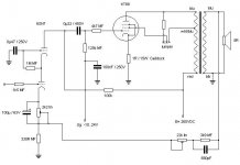
Before ordering my parts, i have been scetching a little and would like your expertise, what should i change to make the circuit better?
Are the workingpoints ok?
Can i lower the feedback in anyway?
Is the drive swing enough to drive the thirsty KT88?
any input are appreciated!!
Before ordering my parts, i have been scetching a little and would like your expertise, what should i change to make the circuit better?
Are the workingpoints ok?
Can i lower the feedback in anyway?
Is the drive swing enough to drive the thirsty KT88?
any input are appreciated!!
Attachments
Hi,
Letsee...
100K to the top 6SN7 is way too big methinks. Try a value that gives you B+/2, without going over dissipation.
You'll want to tie the top 6SN7's grid to a stiff source regulated with a zener or something.
Lose the potentiometers in the NFB. Use fixed resistors (or replace them with fixed resistors once you get it sounding right).
120K on the KT88 grid may bee too big. Try as low a value as possible, without excessive loading of the driver.
Move that screen stopper to right at the socket. It'll be active for both positions, but that's OK.
That's all for now.
Thanks for your input!
So you think i should lower the 6sn7's top anode resistor to, say, about 82k or something like that, half the B+..?
The potentiometers are there temporary, for adjustment..
I lowered the grid resistor for the KT88, but doesn't the -Ug regulate the drive of the KT88?
So you think i should lower the 6sn7's top anode resistor to, say, about 82k or something like that, half the B+..?
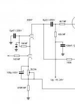
ok, like this or i maybe should remove the cap?6SN7's grid to a stiff source regulated with a zener
The potentiometers are there temporary, for adjustment..
I lowered the grid resistor for the KT88, but doesn't the -Ug regulate the drive of the KT88?
i dont really understand what you mean here? which tube/socket?Move that screen stopper to right at the socket. It'll be active for both positions, but that's OK.
Attachments
Mr. Triatic said:Thanks for your input!
So you think i should lower the 6sn7's top anode resistor to, say, about 82k or something like that, half the B+..?
ok, like this or i maybe should remove the cap?
You're welcome! 🙂
The resistor value will have to be determined experimentally. Do you have this on a breadboard? That would be the easiest.
The procedure to do this is tie the top 6SN7's grid to cathode, directly and have no signal input. Then find the resistor that will give you B+/2. I suspect it will be anywhere from 39K to 82K (I've used cascode, but not with that tube).
Now, we want the zener back in circuit. Keep the Zener config as you have it, but change the resistor from 1M to 330K or 470K and tie it straight to B+, not cathode. You will now want to chose a zener that will give you B+/2 on your plate.
Can't get it perfect with the zeners you have? Use a small voltage divider. Regulation through a small voltage divider is better than none at all.
Why this is important is this point is what's setting your stage gain and transconductance.
Voltage values of 10% are OK.
As for that cap, use a listening test. Theory says it should be there. But what do the noise and sonic dynamics sound like with it there or not there? Which sounds best to you is the right way 🙂
Mr. Triatic said:I lowered the grid resistor for the KT88, but doesn't the -Ug regulate the drive of the KT88?
-Ug just sets the operating point for your KT88.
Since you have a coupling capacitor there, it will do an odd thing as your input voltage comes up to 0V grid on the KT88.. it will store a charge. This stored charge will cause distortion and needs to have "recovery" time through the grid leak resistor. The smaller this resistor, the faster the recovery. But there's a tradeoff - the smaller the resistor, the bigger the load and the more distortion on the driver.
How I find the balance with a high impedance voltmeter or a scope and a sig generator. Turn the amp up to the point where the sine + peaks are hitting 0 bias. You can test this with the voltmeter across the cathode resistor, as the grid will begin drawing a bit of current, or a scope on the grid and look for the waveform distortion. Now, back off on the volume and watch your voltmeter. It will "bump". How long does that bump last? 1/2 second? 1/4 second? Too long will stress the tube. If it's short, you can get away with increasing the resistor some more. I like it to be 1/4 second or so. But my meter needle is different than yours, so that measurement is open to interpretation.
Now you've set the R/C constant of the coupling cap and grid resistor, lets see if the driver has enough grumba. Hook it up to music and turn it up until your voltmeter starts to increase. Sound OK? Leave it. Sound grungy? Try more current through your driver and repeat the steps from the beginning.
You could use the sig gen and scope for that test, but I've had amps that gave great sinewaves, but crappy music. Conversely, sinewaves that were less than perfect, but the amp sounded great.
Sound is all that matters 😉
Mr. Triatic said:i dont really understand what you mean here? which tube/socket?
The KT88
Not meaning to 'jack the thread but, I've just read Geek's post and would like to know if this procedure will work if the lower device is a fet (and upper is a 6sn7)? (especially for finding correct value of anode resistor, and op point)
- Status
- Not open for further replies.
- Home
- Amplifiers
- Tubes / Valves
- KT88 SE with Edcor xfrmr