no sir no 8 watt wimpy design . 2 or 4 tubes each and power i want
Here ya go!
125 watts!!
Point to point wiring, has driver circuit board.
tubes4hifi amplifier KITs page
thank you
i had a look at a modern mullard as mentioned where i found the opus 5.0 ultra pp
downloaded the drawing but i see no value given for c1 and c5.
also this calls for a 4.2k 100w output and got me thinking
what makes the watt level in a tube amp ? the power rails voltage or ther output trans?
The reason for a 100 W. capable O/P trafo is the global NFB loop. Magnetic headroom is needed to accommodate the deep bass error correction signal. The very last thing you want happening is O/P trafo core saturation.
 Guano will smell better than the amp sounds.
Consider that power = V2/R. The active circuitry needs to generate the voltage swing needed in the load. All of the O/P "iron", PSU, and O/P tubes ("finals") have to be appropriately capable, for the desired result to occur. Also, the small signal circuitry must drive the "finals" adequately. Remember the tale of for want of a nail ... a kingdom was lost.
The PSU comes 1st. It is impossible to get a good result, when the PSU is inadequate.
 In formal terms, a good PSU is a necessary, but not sufficient, condition.
thanks
i like the power but not the chassis. never was a fan of dynaco chrome chassis and square.
my design will be 1/8 aluminum plate aprox 10" wide x 14" deep as some of the cary monoblock design.
i have all parts to fab the 2 chassis and iec connectors rca, binding posts as well as some walnut , ash , burl wood , ebony, oak and birds eye maple.
and no chrome
that's for bumpers and faucets ha ha.
at first i was after more power but now i understand that even 60 watts with a 3db headroom will be very good and cheaper to build as well.
anyway this being my first i'm sure not my last unless they turn out to be stellar.
eli
my history is solid state and believe in over building power supplies as cost no object.
these 2 will be no other then top notch as soon as i know what to buy
Last edited:
Money is always an object. When you can get what's needed at "reasonable" cost, do so.
One of these in each channel with the 6.3 V. windings phased up, series wired, and connected to the primary side in the boost configuration will take care of B+. Connect the HV secondaries in parallel and bridge rectify with 4X 600 PIV Schottky diodes.
We'll come up with something suitable for signal tube heater power, along with any negative rails, such as O/P tube bias, that are necessary.
As my brother-in-law lives in Toronto, I'm all too aware of what GST, PST, and duties can do to a Canadian's net expenditures. Mullard circuitry is reasonably tolerant of O/P "iron" that's not "top shelf". With that fact in mind, I checked Canada's Hammond for suitable O/P "iron". Their model 1650R has the requisite power handling capability, but the primary impedance is (IMO) too large for KT88 "finals". Something between 3 Kohms and 3.5 Kohms is "right". Edcor's CXPP100-3.3K is spot on, but you'll have to decide whether or not the ramifications of importation are worth your bother. NAFTA may work to your advantage.
One of these in each channel with the 6.3 V. windings phased up, series wired, and connected to the primary side in the boost configuration will take care of B+. Connect the HV secondaries in parallel and bridge rectify with 4X 600 PIV Schottky diodes.
We'll come up with something suitable for signal tube heater power, along with any negative rails, such as O/P tube bias, that are necessary.
As my brother-in-law lives in Toronto, I'm all too aware of what GST, PST, and duties can do to a Canadian's net expenditures.
Mullard circuitry is reasonably tolerant of O/P "iron" that's not "top shelf". With that fact in mind, I checked Canada's Hammond for suitable O/P "iron". Their model 1650R has the requisite power handling capability, but the primary impedance is (IMO) too large for KT88 "finals". Something between 3 Kohms and 3.5 Kohms is "right". Edcor's CXPP100-3.3K is spot on, but you'll have to decide whether or not the ramifications of importation are worth your bother. NAFTA may work to your advantage.thanks
i like the power but not the chassis. never was a fan of dynaco chrome chassis and square.
my design will be 1/8 aluminum plate aprox 10" wide x 14" deep as some of the cary monoblock design.
i have all parts to fab the 2 chassis and iec connectors rca, binding posts as well as some walnut , ash , burl wood , ebony, oak and birds eye maple.
and no chrome
that's for bumpers and faucets ha ha.
at first i was after more power but now i understand that even 60 watts with a 3db headroom will be very good and cheaper to build as well.
anyway this being my first i'm sure not my last unless they turn out to be stellar.
eli
my history is solid state and believe in over building power supplies as cost no object.
these 2 will be no other then top notch as soon as i know what to buy
You're right, your power supply is the bottleneck to push the amp at 60 Watts.
Good choice on the Kt88, they are more linear than the kt120 in the 30-70 watts region. The good side is that they are smaller tubes requiring less heater current from a less expensive power transfo.
Later you can adjust the bias a little bit lower and install EL34 and KT77 to experience different sounds.
thanks fella's
your ideas here mean the world to me.
i'm over the fear stage now as i started the buy process.
now i'm excited, kt88 quad were aprox $328, other signal tubes were $140, so a good start.
eli
i'm a little confused with opt you mentioned
the opus drawing shows a 100 watt 4.2k is this wrong?
also having a little trouble with the power transformer. edcor show #xpwr214 a 720v 360-0-360 with a 70v for bias and no 5v winding as the drawing show.
can i forget about the 5v leg ?
then just use a edcor #lvp6.3-3.5 6.3 v at 5amp for the filaments.
the 2 power trans will be 410 cdn
the 2 output trans will be 355 cdn
the 2 for filament will be 105 cdn
the 2 chokes will be 76.14 cdn
canadians have to pay twice as much to have fun, but these will be my dream amps.
Last edited:
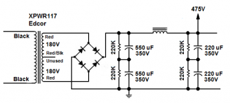
this is the power supply in question
http://www.diyaudio.com/forums/atta...ern-mullard-visio-opus5_0-power-supply_v1.pdf
http://www.diyaudio.com/forums/atta...ern-mullard-visio-opus5_0-power-supply_v1.pdf
I'm a little confused with opt you mentioned the opus drawing shows a 100 watt 4.2k is this wrong?
4.2 Kohms is not "wrong", but also not (IMO) "best". Let's do a voltage swing analysis working back from the load. For an 8 Ω load and 60 W., the P = V2/R formula yields 22 VRMS. The impedance ratio of a trafo varies as the square of the turns ratio. If the primary is 4.2 Kohms, the turns ratio is 23:1. Now,. multiply 22 by 23 and a further 21/2, to get the peak value, and you get 715.6 V. The O/P trafo's primary inductance allows the voltage to swing beyond the value of the B+ rail, but the 475 VDC shown is not likely to pass muster. Run the calculations, for yourself, with a 3.2 Kohm primary and the peak voltage comes in at a less daunting value.
When bucked up by the filament windings, the 325 V. of the AnTek toroid I linked will get somewhere around 500 V. Combine that with the 3.2 Kohm Edcor primary and things will pass muster.
Also, the modestly priced toroid should be good for at least 450 mA. of B+. Can you say GOBS of current in reserve?
Last edited:
Don't purchase anything else until you get your entire schematic finalized. I speak from experience that you will spend less money overall by putting forth some patience until you get your entire circuit finalized. .
Speaking of which, how are you leaning for your audio circuit? Common choices for the Kt88 push pull output stage would be a basic Mullard 5-20 style frontend config, or a Williamson style frontend config. The Mullard front end is a little easier to build and produces great results if executed well. Also I assume you are going to drive your amps with a separate outboard preamp?
. Speaking of which, how are you leaning for your audio circuit? Common choices for the Kt88 push pull output stage would be a basic Mullard 5-20 style frontend config, or a Williamson style frontend config. The Mullard front end is a little easier to build and produces great results if executed well. Also I assume you are going to drive your amps with a separate outboard preamp?
After some additional rumination, I conclude that 1 of these AnTek toroids in each monoblock will be highly satisfactory. No bucking is needed and plenty of heater current is available. While "only" approx. 300 mA. of B+ is available, that still leaves a very substantial amount in reserve.
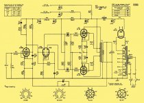
T101 in the "Opus 5.0" PSU schematic seems to be originally intended for use with vacuum rectification. Notice the full wave center tapped (FWCT) topology and 5 VAC winding. That 5 VAC would have been used for filament power in types like the 5U4 and 5AR4.
GKF, a bridge rectifier is more efficient than FWCT. You will use 4X Cree C3D02060F Schottky diodes in each monoblock. CLC filtration with hefty caps. and a Triad C-17X choke follows rectification. Check the archives for my posts about "hash" filters. A "hash" filter deals with both noise riding on the AC mains and the ripple freq. overtone energy inevitable, when large valued caps. are used at the I/P of a PSU filter.
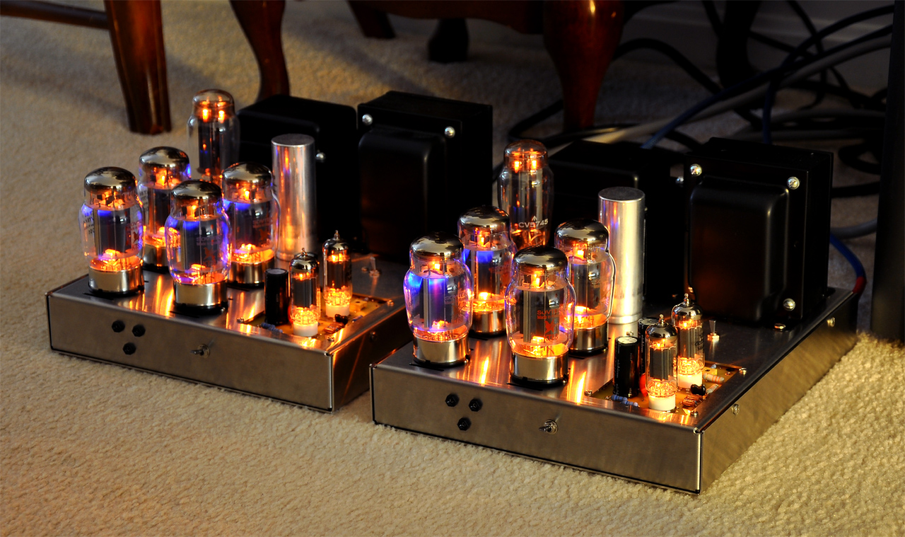
I have essentially built this amp to the specs you identify in post #1. I used the Edcor XPWR117 power transformer--it worked perfectly for my needs. I also built it as a stereo chassis build, so this one power transfomer powered both channels. I used the Triode Electronics A431S output transformers, UL connected output stage, and with fixed bias. With both channels being simultaneously driven I could easily obtain 50 watts per channel output with these components. I was able to barely squeak out 60 watts per channel with bypassed current sense resistors in the cathode circuit of the output stage, but distortion was up just a bit over 50 watts output.
So the Edcor XPWR117 may be another option you want to consider. However, be aware that I had a few quirks and limitations that needed to dealt with:
1. The transformer was a little noisy (buzz when operated). This was not present in the audio output but rather a mechanical buzz from the winding. I addressed this by popping open the end bells and stuffing stiff cardboard in between the bobbin and the iron.
2. It has only a 12V filament winding. I used all AC filaments so I wired the KT120s in two series pairs.
3. No bias tap or bias winding. I solved this by using a low voltage 120V to 12V filament transformer run backwards from the 12V winding of the Edcor (did it this way because it was cheap). Run backwards this way, the small filament transformer is about 85% efficient, but this still gave me plenty of "room" to filter down to the bias voltage I needed (about -60V DC).
The XPRW117 delivered 475V to the center taps of the output transformers under quiescent conditions. The voltages I used offered direct plugability with the KT88 and 6550, which was a requirement for me.
Comparing the Tung Sol new production 6550s to the Tung Sol KT120s, I slightly preferred the 120's, but that's just personal preference. The 120s have commanding control of the bottom end and nice overall buttoned down control over the entire audio spectrum. Both 6550 and KT120, as well as a quad of Winged C 6550s all delivered nearly identical output power (to within a watt).
Distortion with the KT120s installed at 50 watts output, both channels driven was 0.4% THD at 1KHz and under 1% THD from 30 Hz to 15 KHz. The Winged C 6550's delivered a good bit less distortion at full power at the frequency extremes.
eli
i don't understand on toroid . that one is not as the opus stated .
also kward the edcor you said is only 360v
sorry guys i understand you are way more into it then me
but why is the guy who designed the opus calling for 750v ?
i can not understand this
if 360v trans makes 50 watts what does the 750v make?
and why does the design call for it?
The "opus" power supply is using what's called a full wave center-tapped (FWCT) design. Notice the center tap is connected to ground. So with respect to ground, each half of the secondary delivers 1/2 of the end to end voltage. This approach utilizes 50% of the transformer secondary at a time--while the top half is conducting, the bottom half is not, and vice versa. The voltage delivered to the first filter cap is 1/2 of the total voltage from end to end. You need two diodes to make this approach work.
In a full wave bridge (FWB) design, the transformer secondary winding is being utilized 100% of the time. There is no ground connection from the secondary winding directly, rather ground is made virtually at one end of the diode bridge. This is a more efficient use of the secondary winding and generally less expensive to produce. You need four diodes configured in "bridge" layout to make this work.
In both cases, if you have a 360-0-360 secondary used in FWCT, or a 360V secondary used in FWB, and assuming all else is equal, both approaches deliver the same rectified DC voltage output.
See attached FWB wiring example and compare to the "opus".
Attachments
GKF,
The "Opus 5.0" PSU uses FWCT topology. The rectifier winding is 375-0-375. Each of the diodes needs to withstand 750 VRMS (the end to end voltage of the rectifier winding), but the B+ rail comes in at 530 VDC, less losses. (21/2) (375) = 530 Bridge rectifying the 350 VRMS of the AnTek toroid yields 495 VDC, less losses.
Remember, P = V2/R. Also, look back at the voltage swing analysis I previously provided. The B+ PSU has to have sufficient "stones" in both the voltage and current departments. Otherwise, the desired result will not be obtained. Bridge rectifying and correct CLC filtering an AnTek AS-2T350 will get the job done, in combination with the Edcor O/P "iron" already ordered. Edcor's stuff has a smaller step down ratio than shown in "Opus 5.0".
guys my head is spinning
all i want is the single best it can be. but i need a design to build from another that is followed to the letter.
i can build anything i just do not know what i'm doing here.
i've built lots of solid state amps and know there power supply.
but just don't get a toroid in a tube amp when look is very important.
i mean it will look funny with a square opt beside it.
or can a toroid be made for a opt to match?
i just think all the great amps made use iron and these need iron for the correct look.
but can square cover be use over the toroid trans?
sorry , i know i must frustrate both of you
i just know what i want but have trouble getting there.
i even have the chassis 's cut out and ready to weld the aluminum parts .
thanks
gordie
Can square cover be use over the toroid trans?
Certainly! Another possibility is mounting the toroid on the underside of the plate and using an "acorn" nut topside, for a finished appearance.
You will get better shielding, if you use sheet copper or adhesive copper tape on the inside of your wooden frames. Leave yourself plenty of room, in all 3 (X Y Z) spatial planes. "Better to be looking at it than needing it."
Consider using metal housing Neutrik RCA jacks mounted in the wood frames, to gain top plate space and (IMO) a better look.
When I said look for "Modern Mullard", it was intended to get the thought process started. The seminal design for Mullard style circuitry is the 5-20. Notice the key features of a voltage amplifier DC coupled to a long tailed pair (LTP) phase splitter, and cap. coupled "finals". Don't "cookie cutter". Instead, follow the trail blazed for some time and then branch off. Parts undreamed of in the "Golden Age" are currently available that allow for a higher level of performance. That which was very good, to begin with, gets better.
GKF, do you have access to an oscilloscope? If not, a brute force method of phase compensation is available that yields quite acceptable results.
Attachments
guys my head is spinning
all i want is the single best it can be. but i need a design to build from another that is followed to the letter.
<snip>
gordie
Then buy a Dynaco MkIII from dynakitparts. It has a parts you need with a proven
schematics and proven track record. In addition you may sell it for the amount you bought it from when / if you want something else.
Last edited:
Then buy a Dynaco MkIII from dynakitparts. It has a parts you need with a proven
schematics and proven track record. In addition you may sell it for the amount you bought it from when / if you want something else.
Or tubes4hifi.com, which seems to now use parts from dynakitparts. Been running amps cobbled together from tubes4hifi boards and iron and chassis from triodeelectronics.com, for more than 15 years. Relatively compact, sweet sounding to my aging ears, and reliable. I want for nothing. Not sure what may have changed since my investment, but I would do it again today in a heartbeat.
A MkIII may not be an exemplar of amp design, but mine have had no fear of any speaker I have thrown at it. Currently, they drive NHT 3.3s, which are notoriously hungry, and weigh a ton, making them an annoyance to move around. Pretty sure, only some Maggies could take them down (just a guess).
Then buy a Dynaco MkIII
thanks but no, the dynaco ship has sailed away. let it go
i'm after way beyond dynaco new or old.
eli has a very good idea with the power toroid under the chassis.
this sounds very interesting enough that i'm remodeling my chassis layout for this.
now another question has come up, i bought a psvane quad black label from there website direct. emailed a question to them about power output and power transformer needs. they tell me to never apply anymore then 560v to a pair.
also below that will yeild from 70 to 90 watts with modest distortion .
so eli will that mean the toroid will be at 500v to the plates? and is that what psvane mean?
does a tube amp require dc through the circuit or ac?
- Status
- This old topic is closed. If you want to reopen this topic, contact a moderator using the "Report Post" button.
- Home
- Amplifiers
- Tubes / Valves
- KT88 pp monobloc thoughts