Hello,
I am an electronic engineering technologist student, and for my capstone project I am building a stereo amplifier using a solid state front end and a tube power amplifier. One of the requirements for the amplifier is that an ARM microprocessor be used somehow. I have decided to use the microprocessor to control the volume, bass/treble control, speaker balance and input select.
I have always been facinated with vacuum tubes and thought it would be a good idea to incorporate it into my ampliifer. The tubes I have chosen are KT88's (I bought 4 matched Electro-Harmonix tubes) in a class AB configuration. I want the power output to be 50-75 watt per channel with THD <%1. Since I have never built a tube amplifier before I would like some suggestions from you guys.
One of my main concerns is combining a solid state pre-amplifier with a tube amplifier. I can't find a lot of information on this setup, so any comments or information sources would be greatly appreciated.
Is there anyone who has experience with implementing digital potentiometers in an amplifier? They seem pretty straight forward. Also, could there be noise issues with running an analog signal through a digital pot?
Thanks
Sorry I have no experience with digital pots (the concept causes uncontrolled twitching in my right eye for some reason 😉) but I have a couple of thoughts for you. Since you are going to have a micro processor in there maybe it could be used to mange the output tube bias as well.
Another possibility is to use motorized pots (or step attenuators) with the motors or relays controlled by the micro processor.
If you are going SS front end I would resist the temptation to use high gain high FB devices like op amps. Are you doing phono preamp also or just line amp in the front end? Simple discrete jFET front end would seem to be most in keeping with the output stage you are planning. I can't help with the details but it seems that I have read here some posts on using local FB on FETs to get very triode like characteristics.
Hmmm...THD < 1% - why? As long as the solid state section behaves and only the tubes produce harmonics you can allow much more than that.
You mainly get k2, one octave above the signal, and that fits in very nicely.
Clobbering tubes into submission by using too much feedback (word?) makes them sound as lively as old socks.
You mainly get k2, one octave above the signal, and that fits in very nicely.
Clobbering tubes into submission by using too much feedback (word?) makes them sound as lively as old socks.
P.S. As to the digital pot - you might contact Ed Schilling at
the horn shoppe
Tell him I´ll send Helen a kiss and three hugs if he shares a bit of electronic sorcery with you.
Pit
(Don´t phone him when you are pressed for time - that man doesn´t believe in two-minutes-info)
the horn shoppe
Tell him I´ll send Helen a kiss and three hugs if he shares a bit of electronic sorcery with you.
Pit
(Don´t phone him when you are pressed for time - that man doesn´t believe in two-minutes-info)
Last edited:
I would recommend, say, a Pass front end of some kind...maybe a JFETBOZ or something...couple that output to your KT88 power stage and whatever add-ons you want and you will have something that sounds very nice.
I was using my JFETBOZ as preamp for my simpleSE using KT88s and it sounded very nice. I would imagine in PP configuration the power would be ample...
I was using my JFETBOZ as preamp for my simpleSE using KT88s and it sounded very nice. I would imagine in PP configuration the power would be ample...
Good suggestions have been made. Do what's necessary to get a modest gain "sand" front end that's linear. Then, you will have enough Volts to use a 12AT7 based differential splitter/driver, like that found in "El Cheapo" (schematic attached).
UltraLinear mode "finals" will get you the power you desire. Enough loop NFB is present to provide a decent damping factor and a THD under 1%.
The 'T7 sounds good with 200 to 220 V. on the plate and an IB of 3 mA.
Edcor's model CXPP100-MS-3.3K O/P trafo will give good results, without making you destitute.
Attachments
One of the requirements for the amplifier is that an ARM microprocessor be used somehow.
I have put chips and tubes together several times. About 15 years ago I built a guitar amp using a SS front end and tubes for output. All of it was controlled by a PIC processor. At the time National Semiconductor made a stereo preamp chip which had the volume, bass, treble, and balance functions controllable via SPI. They also made an equalizer chip. I used some Panasonic rotary encoders, and LED readouts for a cool amp.
More recently I used a dsPIC chip to do active power supply modulation (Class H operation) on a vacuum tube amplifier. It was entered into a design contest sponsored by Circuit Cellar magazine where it won a prize, and lead to me writing a magazine article about it.
Why am I telling you this? Well it seems that Circuit Cellar and Elektor are running another contest. They want the world to learn about NXP's (formerly Philips) new MBED board. First there was the Basic Stamp, then came Arduino. Now there is MBED. MBED is a tiny board resembling the DIP version of the Basic Stamp. It contains an ARM Cortex M3 chip with plenty of processing power. The new unique twist here is that you program it via the web. THe compiler resides in the "cloud." If you fill out a form on the contest page they will send you one of the boards absolutely FREE. I got mine last week. If someone likes your entry, you could win cash. If you write an article about it you could get a job offer, or even a phone call from a CEO.
NXP mbed Design Challenge
Yes, I'm going to enter something. It will have tubes and chips, but it won't be a stereo amp.
Thanks everyone for the informative replies. I definately will consider everyone's opinion. I am sure I will have plenty of more questions as the project moves forward. I'll keep you posted as I make progress.
I have put chips and tubes together several times. About 15 years ago I built a guitar amp using a SS front end and tubes for output. All of it was controlled by a PIC processor. At the time National Semiconductor made a stereo preamp chip which had the volume, bass, treble, and balance functions controllable via SPI. They also made an equalizer chip. I used some Panasonic rotary encoders, and LED readouts for a cool amp.
More recently I used a dsPIC chip to do active power supply modulation (Class H operation) on a vacuum tube amplifier. It was entered into a design contest sponsored by Circuit Cellar magazine where it won a prize, and lead to me writing a magazine article about it.
Why am I telling you this? Well it seems that Circuit Cellar and Elektor are running another contest. They want the world to learn about NXP's (formerly Philips) new MBED board. First there was the Basic Stamp, then came Arduino. Now there is MBED. MBED is a tiny board resembling the DIP version of the Basic Stamp. It contains an ARM Cortex M3 chip with plenty of processing power. The new unique twist here is that you program it via the web. THe compiler resides in the "cloud." If you fill out a form on the contest page they will send you one of the boards absolutely FREE. I got mine last week. If someone likes your entry, you could win cash. If you write an article about it you could get a job offer, or even a phone call from a CEO.
NXP mbed Design Challenge
Yes, I'm going to enter something. It will have tubes and chips, but it won't be a stereo amp.
They ran out. so no more "free"
Why am I telling you this? Well it seems that Circuit Cellar and Elektor are running another contest. They want the world to learn about NXP's (formerly Philips) new MBED board. First there was the Basic Stamp, then came Arduino. Now there is MBED. MBED is a tiny board resembling the DIP version of the Basic Stamp. It contains an ARM Cortex M3 chip with plenty of processing power. The new unique twist here is that you program it via the web. THe compiler resides in the "cloud." If you fill out a form on the contest page they will send you one of the boards absolutely FREE. I got mine last week. If someone likes your entry, you could win cash. If you write an article about it you could get a job offer, or even a phone call from a CEO.
NXP mbed Design Challenge
Yes, I'm going to enter something. It will have tubes and chips, but it won't be a stereo amp.
Wow!
Thank you George for the information!
I am going to check if a mammoth can reincarnate into a butterfly instead of dying according to Darwin's theory. I have some nice project in mind with CPU, ADC and a TFT display!
Amplifier is DONE!
Hello All!
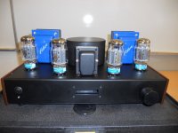
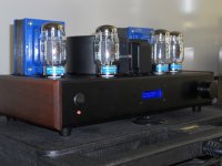
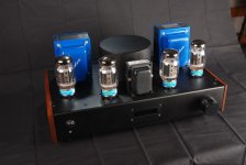
The amplifier is done so I thought I would share it with everyone here.
Overview
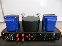
The power amplifier is a stereo push pull ultra linear configuration using KT88's. The plate voltage is set to a regulated 480V and provides 45W of power. The output transformers are EDCOR 5K 100W with 16, 8 and 4 Ohm secondaries. The power amplifier design is taken from AudioXpress magazine where the designer Bill Christie used an LM4702 to drive the KT88's.
The entire pre amplifier is solid state and microprocessor controlled. I used the TDA7439 audio processor chip for the preamp. It has a 3-band equalizer (bass, mid, treble), 4 input multiplexer. volume and balance control. A MAKE controller with the ATMEL SAM7x microprocessor controls the chip.
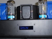
The user interface was designed to be as sleek as possible. One quadrature shaft encoder allows the user to change the audio settings. Pushing the knob switches between the menus: volume, bass, mid, treble, balance, input select, LCD display contrast and pre-amp bypass. Turning the knob then changes the settings. The pre amp bypass allows the user to use only the power amp if an external preamp is available. A separate RCA input is at the back of the amplifier for the power amp only.
All voltages are regulated except the filament voltages. Each channel has its own Maida regulator. The voltage on the LM4702 is set to +/- 65 volts also using a Maida regulator.
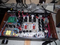
I bought the basic chassis over ebay and punch and drilled the holes myself. I then had the chassis powder coated. There are two low noise fans that blow air into the chassis and out through holes drilled around each tube for added cooling.
I am a student in an Electronics engineering technology program and this amplifier was for my capstone project. I was in a group of three people and I was responsible for the power supplies and the tube power amplifier. It is the first tube amplifier I ever built and definitely not the last. It's not perfect by any means but sounds really good. I would like to thank all of you who gave me their advice and ideas. This project would not have been a success if it not were for this forum. Here are some pics!
Hello All!
The amplifier is done so I thought I would share it with everyone here.
Overview
The power amplifier is a stereo push pull ultra linear configuration using KT88's. The plate voltage is set to a regulated 480V and provides 45W of power. The output transformers are EDCOR 5K 100W with 16, 8 and 4 Ohm secondaries. The power amplifier design is taken from AudioXpress magazine where the designer Bill Christie used an LM4702 to drive the KT88's.
The entire pre amplifier is solid state and microprocessor controlled. I used the TDA7439 audio processor chip for the preamp. It has a 3-band equalizer (bass, mid, treble), 4 input multiplexer. volume and balance control. A MAKE controller with the ATMEL SAM7x microprocessor controls the chip.
The user interface was designed to be as sleek as possible. One quadrature shaft encoder allows the user to change the audio settings. Pushing the knob switches between the menus: volume, bass, mid, treble, balance, input select, LCD display contrast and pre-amp bypass. Turning the knob then changes the settings. The pre amp bypass allows the user to use only the power amp if an external preamp is available. A separate RCA input is at the back of the amplifier for the power amp only.
All voltages are regulated except the filament voltages. Each channel has its own Maida regulator. The voltage on the LM4702 is set to +/- 65 volts also using a Maida regulator.
I bought the basic chassis over ebay and punch and drilled the holes myself. I then had the chassis powder coated. There are two low noise fans that blow air into the chassis and out through holes drilled around each tube for added cooling.
I am a student in an Electronics engineering technology program and this amplifier was for my capstone project. I was in a group of three people and I was responsible for the power supplies and the tube power amplifier. It is the first tube amplifier I ever built and definitely not the last. It's not perfect by any means but sounds really good. I would like to thank all of you who gave me their advice and ideas. This project would not have been a success if it not were for this forum. Here are some pics!
Attachments
- Status
- Not open for further replies.
- Home
- Amplifiers
- Tubes / Valves
- KT88 hybrid amplifier