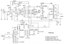
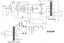
I was serching and I found this schematic design of a KT88 amp, I'm not a tube expert but I would like to know if this circuit can behave well, my questions is why the guys use 8 1N4007 diodes? why not tube rectifier? I would like to try it out but the only think that got me stop is the power supply design, I will appreciated if you guys can help me with better alternatives but if diodes are ok is fine, here is the copy I made of the schematic and the original that does not look define.
Best Regards
Juan
Best Regards
Juan
Attachments

Last edited:
Well, four of those diodes are for the bias voltage... diodes are cheaper than any other rectifier, and work just fine.
Instead 4 worst diodes 1N4007 for PS, You can use Fast diodes BYV26E. Or kenotron GZ34, but +U will decrease with about 10 v. /4 upper 1N4007 are good for bias/.
UF4007 are a newer, faster, & quieter diode for a few cents more each. As mentioned better for the power supply at least.
Also if your buying OPTs (output transformer) the Hammond 1650R is much better than the 1650N on second schem.
Also if your buying OPTs (output transformer) the Hammond 1650R is much better than the 1650N on second schem.
Last edited:
Vargasmongo,
Yes, better now with 6P6s. I was going to suggest at least ECC88s instead of ECC81 and ECC83.
Small point: I am uncomfortable with simply using diodes in series without some sort of voltage dividing network. Without that the division of inverse voltge between the two may not be equal. As far as I know reverse leakage is not a defined value, and there is also capacitance. Thus one may temporarily have much more reverse voltage over it than the other. There are enough high-V diodes available these days.
Vargasmongo,
Yes, better now with 6P6s. I was going to suggest at least ECC88s instead of ECC81 and ECC83.
Small point: I am uncomfortable with simply using diodes in series without some sort of voltage dividing network. Without that the division of inverse voltge between the two may not be equal. As far as I know reverse leakage is not a defined value, and there is also capacitance. Thus one may temporarily have much more reverse voltage over it than the other. There are enough high-V diodes available these days.
ECC88 uhmm ok I will check that out, and yes I was wandering about the power supply design 4 diodes for the power supply does not look completely
right I was thinking maybe will be just fine to only have two diodes but with higher voltage tolerance I was searching and reading and I've not seen a similar power supply configuration. I will post what the original guy designer post in his website.
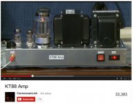
Original designer information down below and also some image of YouTube video and images.
Designers link: http://www.freewebs.com/cameramanlink/electronicsprojects.htm
here is his video link: KT88 Amp - YouTube
" The KT88 Amp is the result of an effort to improve upon the previously-posted 50W Amp. The 50W Amp's power output was measured to be only 30W! This was quite a problem as the schematic said that it should put out 60W max. This led me to look for different designs for push-pull amplifiers based around the KT88 tubes and Hammond output transformer I recycled from the previous project. The first schematic I came to was one in Kevin O'Connor's book "Principles of Power." This had a circuit diagram for a KT88 amp that ran on a negative voltage supply for the cathodes, and the usual positive power supply for the plates. When I tried this, I got extreme symmetry problems with the positive spikes being pointy and the troughs being big and rounded. I scrapped the negative power supply and used a typical power supply configuration. I also changed the cathode circuits to use resistors to ground rather than a negative voltage. After fiddling around with some values for the negative feedback, I got it to work quite nicely. The gain is low so it needs a preamp, but it can now put out the expected 60W max power. The symmetry problem was solved and it sounds great! My desire to make the circuit more compact led me to use the size of box that I did. It was either this size or the huge box I used before. Soldering the components in place was tight but it worked out in the end and there aren't interference problems. If I had two of these they would make a great pair for a home hi-fi stereo system. "
the designer is a young guy and he already made many tube amplifier model also for guitars too, the reason I like the KT88 AMP is because look really nice to have because of the simplicity look.
I like the way it looks and resembles the Dynaco MKIII looks just a little bit like Dynaco not an exact look but is similar.
About the power supply that is the only part of the circuit that worried me you guys think that will be ok with only two diodes but as a mention with higher voltage tolerance instead of 4?
about the preamp stage ECC88 will perform better for the driver stage? I'm all ears willing to change it to make it even better if possible I will apreciate all help.
Best Regards
Juan
Attachments


- Status
- Not open for further replies.
- Home
- Amplifiers
- Tubes / Valves
- KT88 amp questions