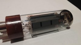
So far I haven't incinerated any power tubes, I have no idea who manufactured the EL34's I have.. I'll post a pic.
I like the soft warm glow of the tube rectifier, I don't think I'll stray away from tube rectification, at least not with this project. I was thinking of adding an RC stage to my power supply to bring the voltage down a bit. I really don't care for the sound of the KT150's.. perhaps because they haven't burned in yet.. I much prefer the EL34's.
I like the soft warm glow of the tube rectifier, I don't think I'll stray away from tube rectification, at least not with this project. I was thinking of adding an RC stage to my power supply to bring the voltage down a bit. I really don't care for the sound of the KT150's.. perhaps because they haven't burned in yet.. I much prefer the EL34's.
Attachments
Canadatubedude,
two comments on your schematics:
1st, if you actually wire your step attenuator this way, i.e. with it's wiper returned to gnd, your amplifier never ever will delight you with playing music.
2nd, I'd wire the EL34/6L6 560R cathode resistor between pins 1/8 to gnd and switch a 910R in parallel as the KT option. This saves a SPDT switch in favour of a - often cheaper - SPST one.
Best regards!
@ Kay - Could you explain what you mean with your first statement? Regarding the grounding of the attenuator..
As for the switch, I already have a DPDT (on-on) switch installed, I don't think it's shown properly in the schematic.
As for the switch, I already have a DPDT (on-on) switch installed, I don't think it's shown properly in the schematic.
having one of these amps myself, I will recomend 2-5ar4's in parrell. the sag is going to be alot with one tube, if it'll run at all.
that much load might be why you blew the rectifier tube.
My two cents Stu
that much load might be why you blew the rectifier tube.
My two cents Stu
Appreciate the input srb02,
I'm not in a position to install another octal socket for a second rectifier, and my rectifier filament transformer is limited to 3 amps. I don't notice any sag, it's Class A so it's drawing constant current.
I need to find a solution using a single octal rectifier (ideally indirectly heated), with a filament current no more than 3 amps. The 5AR4 ran the amplifier just fine, but I turned it on while the tubes were still hot and the current was too great, rectifier arc'd and my mains fuse blew.
I know this whole project started as a KT150 Single Ended Class A amplifier, but I'm really not liking the sound of the KT150. It's very clear, and tight.. but sterile and lifeless, inorganic.
I'm wondering if a set of Genelex KT77's are in order for this amplifier. Absolute max dissipation of 32watts, which is pretty close to what I'm running with the EL34's (which are beyond max dissipation).
@ Kay - Could you explain what you mean with your first statement? Regarding the grounding of the attenuator..
Of course. Your schematics show one end of the attenuator going to the input jack, the other end going to the first grid, and the 'wiper' (if it were a potentiometer) going to ground. So there isn't any chance at all for the input signal to get to the grid. Additionally, when the wiper comes to the left hand side, there's a short circuit to the input signal. Not too good for some sources...
Best regards!
You can install diodes before the rectifier, that could help.
400vac --- Di ---- Rectifier pin
0 ---- Ground
400vac --- Di ---- Rectifier pin
Are you sure the 5ar4 rectifier is killed???
I did the same thing to many rectifiers and it never affected the performance.
Mainly with amplifier which draw lot of current it is prone to sparks, installing 2 in parallel could help but not an option for you unfortunately (3A).
400vac --- Di ---- Rectifier pin
0 ---- Ground
400vac --- Di ---- Rectifier pin
Are you sure the 5ar4 rectifier is killed???
I did the same thing to many rectifiers and it never affected the performance.
Mainly with amplifier which draw lot of current it is prone to sparks, installing 2 in parallel could help but not an option for you unfortunately (3A).
@ Kay - Ahh.. I understand. The schematic must not be correct, I have the attenuator hooked up and it appears to be functioning properly. I thought you may have been referring to the absence of a ~500k resistor going from 6SN7 grid to ground (between the attenuator and tube itself. I see this on schematics, and I'm not sure what the purpose is. Thanks for the advice!
@ gabdx - I'm assuming the tube is killed, I don't know for sure.. there was a BRIGHT blue/violent flash when it failed (inside the tube). Makes me think something inside has melted, and I don't really want to take the chance putting it back in. I think I may go with limiting resistors on the HV secondaries feeding the 5AR4 as listed in the RCA datasheet. I do have uf4007 diodes kicking around though.. options are good.
@ gabdx - I'm assuming the tube is killed, I don't know for sure.. there was a BRIGHT blue/violent flash when it failed (inside the tube). Makes me think something inside has melted, and I don't really want to take the chance putting it back in. I think I may go with limiting resistors on the HV secondaries feeding the 5AR4 as listed in the RCA datasheet. I do have uf4007 diodes kicking around though.. options are good.
"but I'm really not liking the sound of the KT150.It's very clear,and tight.. but sterile and lifeless,inorganic."
The marriage of 2 revealing valves will do that to you.How about trying a pentode driver instead.
The marriage of 2 revealing valves will do that to you.How about trying a pentode driver instead.
@ gabdx - FYI you're a driving force behind this project.. I basically took your advise from post #18 and ran with it.
I would hold off giving up on the KT-150s until they're broken in. I've heard good sounding warm KT-150 amps but the tubes take 50-100 hours of break-in to get there. My EH KT-88s took about 100 hours before they had enough bass, for example.
EL34?
Why not.It's been suggested already...#18.No need to cut any more holes in your chassis.That Noval socket can be used for a 6CG7 =6SN7.
Don't give up on your KT150s 'dude
Why not.It's been suggested already...#18.No need to cut any more holes in your chassis.That Noval socket can be used for a 6CG7 =6SN7.
Don't give up on your KT150s 'dude
Well I paid for the KT150's, so I'm not going to give up on them. It's the midrange that I feel they're lacking.
Update
Okay, so the KT150's have had time to burn in, and now they're sounding great. The bass extension is DEEP, midrange is nice and clear, and the highs are crisp. My default go-to test track is "Thanks to you" - Boz Scaggs, and it sounds marvelous.
Got a new 5AR4 (JJ, was cheap) and I've updated the PS from CLC to CLCRC with 250R (2x 10w 500R) resistance to account for the increase in voltage with the 5AR4.
Everything seems to be working fine, as long as I don't hot switch it.
Likely going to be adding some resistance to the High Voltage secondaries where they enter the rectifier as per the 5AR4 datasheet.
Really diggin' the KT150's, now I just need to find a purpose for one noval tube that I have room for.
All that's left is to tweak the operating point for the KT150's
A couple of years they were really bad. (Just the JJ 5AR4) I threw the one I had away.Got a new 5AR4 (JJ, was cheap)
Looks like they still suck.
..and the 5AR4 just nuked itself.
Turned it off, and then back on again about 5 seconds later.. lightshow, rectifier is toasted.
Surge voltage I'm thinking..
This is called "hot switching" and is a big no no with tube rectifiers. That will arc your rectifier but sometimes it won't toast it. As others have said you need to wait a few minutes (to be safe) before turning on the amp after it has been turned off.
Also i am not sure if the 5v4g or ga has enough current capability for your use. "design center value" is 375v per plate at 175ma. At higher voltages the max current will drop quickly. According to Sylvania tube manual.
I'm pretty sure the 5AR4 that I arced is toast.. sounds like something is rattling around inside the tube (not the usual sounds). Good opportunity to take it apart as a learning experience. And yeah, I've learned about hot switching the hard way. I'm going to go with the 5AR4 for now, but it's got to be operating near maximum. I calculate ~180mA draw between the KT150's and 6SN7's in it's current configuration, not sure if the RC stage in the PS adds current to that calculation. If I'm reading the datasheet correctly, the 5AR4 can do 225mA @450v and I'm running the B+ closer to 500v.
A couple of years they were really bad. (Just the JJ 5AR4) I threw the one I had away.
Looks like they still suck.
Seems to work so far. Maybe I'll replace it later if JJ is junk.
- Home
- Amplifiers
- Tubes / Valves
- KT150 SE based on Mikael's KT88 Schematic