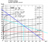
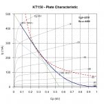
I worked up a loadline for this type. Looks like it can do 75W easy, and without going too far into Class AB. The primary load looks like 8K8 will be good, and that's probably a stock value. Not enough detail to extrapolate a likely h3 estimate, but this is a simplistic estimate anyway that depends on a lot of assumptions. Says nothing as to how the circuit actually sounds, and that's a matter of listen and learn, seeing that it depends heavily on the actual harmonic profile of the harmonic distortion. H3 isn't so bad (mostly an edgy, overly aggressive sound); it's the higher order harmonics that sound really bad. In any case, you'll be needing some NFB to clean up whatever harmonic messes open loop operation produces.
Attachments
thank you Miles Prower for your load line help...
i have in mind a 4.4k opt design, i can try loading the 8 ohm speaker to the 4 ohm tap..
i will be using the radford front end in this build if ever it materializes...

i have in mind a 4.4k opt design, i can try loading the 8 ohm speaker to the 4 ohm tap..
i will be using the radford front end in this build if ever it materializes...
You are welcome, it would be interesting to find out how the actual tubes bias up, because Tung-Sol's datasheets for the KT120 and KT150 are kinda sketchy.
I have Sofia in service at Audiomatica so I can in next future to test in deep the KT150
On the lasts diagram I can't understand why we have to set the bias point so the 150 will dissipate almost the 85% of the Pa to reach in a good power in AB?
I will use this set for a full class A amp, in case.
My opinion
Walter
On the lasts diagram I can't understand why we have to set the bias point so the 150 will dissipate almost the 85% of the Pa to reach in a good power in AB?
I will use this set for a full class A amp, in case.
My opinion
Walter
Also -22 v of bias it is a problem for driver because you will go into A2 easily and there is no reason to do this in AB
My opinion
Walter
My opinion
Walter
80% of plate dissipation is considered not too hot for a class ab amp..
so for a 60 watt plate, 48 watts at idle is not so bad...
now that is 96 watts at idle so that the class A window is indeed significant...
in many cases, you need not go out of classA to transition to class AB, maybe power is enough...
and this is what i am counting on doing the kt150...
so for a 60 watt plate, 48 watts at idle is not so bad...
now that is 96 watts at idle so that the class A window is indeed significant...
in many cases, you need not go out of classA to transition to class AB, maybe power is enough...
and this is what i am counting on doing the kt150...
look at bias point
are 54 watt as miles said and more looking at your diagram
Walter
Hmm, 550 x 0.0832 = 46, 46/70 = 0.65. Not 0.85. 😉
Ok, my error on typing but the concept is the same
No reason to have this dissipation in AB configuration.
This is the wrong way, in my opinion, to reach a fine class AB amp.
The bias point a -22 v, as said before, is not good.
Walter
No reason to have this dissipation in AB configuration.
This is the wrong way, in my opinion, to reach a fine class AB amp.
The bias point a -22 v, as said before, is not good.
Walter
Ok, my error on typing but the concept is the same
No reason to have this dissipation in AB configuration.
This is the wrong way, in my opinion, to reach a fine class AB amp.
The bias point a -22 v, as said before, is not good.
Walter
care to explain please..
another thing i am looking at is the grid leak resistors for the kt150,
for tubes this big, it seems that lower, say 47k is required for fixed bias,
so cathode followers seem mandatory...
What Tony wants, Tony gets... 🙂 He will let us know how the bias works out... or not.
seldom happens that what is on the paper happens in real world,
with tubes that is...
As you imaging if you connect the g2 by 1K resistor to Vdc the bias point goes around -40 vdc ( I have to check better on my other amp with same conf) In this way you can set the Ibias at, p.e., 40 mA so you can run in full class A until 4-5 watt, the previous stage is not a risk of to drive in A2 the 150 grid, you haven't to use maybe an additional gain stage to drive properly the CF and the life on power tube will be longer.
If you use the 6922 + 6H30 you will get a great swing with low distortion and a reasonable low Zout of the splitter
The resistor grid I use for each 150 in fixed bias is 180K-270 K without any type of problems..
After that you must use a good OT otherwise all consideration are not logic.
My opinion
Walter
Nah. Just use a decent tube like the 6N6P or ECC99.care to explain please..
another thing i am looking at is the grid leak resistors for the kt150,
for tubes this big, it seems that lower, say 47k is required for fixed bias,
so cathode followers seem mandatory...
I'm using one into a 47k load on my Stupendous Amplifier.
See here: The Stupendous 6P1P 4PP amplifier!
KT150's are Very expensive why would you use them Instead of 6550's or KT88's for only 60 watts?
47k Grid leak is recommended for current production KT88's, 6550's not 100k as recommended for GEC KT88, yet you see so many amps using 100K or higher; I think is best to use 39 K for current production tubes; I use 6N6 and cathode followers { 6BL7}
47k Grid leak is recommended for current production KT88's, 6550's not 100k as recommended for GEC KT88, yet you see so many amps using 100K or higher; I think is best to use 39 K for current production tubes; I use 6N6 and cathode followers { 6BL7}
- Status
- Not open for further replies.
- Home
- Amplifiers
- Tubes / Valves
- KT150 pp amp operating points please

